Wow. Those VW engineers – every time they improve something, they create another problem. They add more lights so they add more wires. They add a “computerized” testing system (VW’s prehistoric version of on board diagnosis from the early seventies to sometime later) and they add even more wires. But they do sometimes add cookies, but then you probably won’t get any milk. And then they added water, and now you have the potential for at least 100 new places to leak except this time it’s water instead of oil. And when it’s water, it’s often a catastrophic leak and there’s a lot of places for them to happen to the odds are high that you’ll probably have to walk. With oil, you can usually just keep pouring it in providing you have up to maybe a whole case of the stuff. Unless the flywheel seal fell out or it’s crispy or it’s a real leaky oil cooler or real, real, real crispy oil cooler seals. Then you might have to walk. Oh, and sometimes they add a new idea in the form of new, never before needed oil galley in the engine case and you get more oil light on. I don’t know what they were drinking that night. And I’d be really interested in finding out what these guys were on when they decided try to fool the
ALL POWERFUL AND ALL KNOWING FEDERAL GOVERNMENT OF THE UNITED STATES
and maybe a lot of other federal governments too. What were these guys thinking??????? I wonder who exactly gave the ok for this. It’s seems criminal. It’s certainly a REALLY BIG LIE. I’m wondering what effect this may have on the rear engined VW industry. It’s obvious there’s gonna be a sea change at VW. I still see some parts with VW/Audi emblems on them . Late air cooled shift couplings for instance. Supposedly made in Germany, not Brazil. There’s no way they’re NOS. They look like they were made yesterday. But they’re so poorly made, I seriously wonder if they’re counterfeit. No kidding. But if these parts are actually real, they may go away if VW is making them, regardless of where. They may delete it all. They’re gonna have to do some severe cost cutting. Maybe delete or sell some of there more their more extraneous ventures. And their image is severely tarnished so they’re gonna see a drop in revenues. And you know that started the moment this news came out. We’ll see happens. Regardless, what VW got caught doing – unfrickfucknbelievable. Shocking. VW apologized to everyone they’ve hurt. They’re sorry.
They were warned about this 2 years ago. They did nothing. The software is was originally delivered as test software created by Bosch. Bosch told them not to use if for any other purpose in 2007. They made a real bad decision. Their repentance could cost them up to, but not likely, 18 billion in the US alone. From what I’ve read, it’s not likely they’ll have to pay that much.
Here’s what happens when an individual issues fake smog certifications in Nevada. He was in federal custody when the article in the link was current a few years ago ….
http://www.reviewjournal.com/news/feds-foil-family-s-fake-smog-check-scheme
I wonder if any of those directly responsible for this at VW will serve any time. But I’m certain there’s quite a few VW executives are having a real hard time sleeping lately.
VW sold 11 million of the affected cars worldwide. And only about a half million in he US. If the fine for the other 10.5 million is “only” five grand each – much lower than the 37, 500 maximum possible in the US, the total would be a whopping …
$$SEVENTY FIVE BILLION DOLLARS$$
That’s a lot.
Everything I write adds up to 5 and I do my best to be sure that 5 really is the correct answer. Except for the my thoughts regarding VW’s future in the my first chunk of text. A paragraph I suppose. It’s just speculation based on a lot of reality. But anyway, that’s the maximum. Just 5. It’s meant to mean the same thing as a ten but I just like to type the word five. Five. Ahhh …. It’s also because all cars are a 5. They’re not perfect. Like the points. Setting the points right is setting them like they’re supposed to be so they’ll last as long as possible. Not perfect, just adjusted so they work right and last a long time. As good as the car came new. There’s really no variability when setting the points. Just do it like the guys who made the car did it. It’s easy. They’ll last a long time. Click this to see how it’s done. Points are discussed about halfway down the very long page. But start reading at the text beginning under heading regarding the distributor located right above the point discussion. If you choose to read it all, you’ll get my point. And learn the pros and cons of opting for electronic ignition. That’s in the point discussion.
Air cooled VW’s . Reliable, trustworthy, but still an imperfect mechanical contraption. That’s why your sump plate needs tightening about once a month so it won’t leave a spot (if you drive the car daily and get the engine nice an hot when you do). Sometimes, I find a new correct answer. A previous five instantly turns into a zero. No one who works on a VW, no matter how long, has seen everything. One’s age would have to surpass that of the remaining lifetime of the universe for that to happen and from what I hear, there’s a 50 percent chance the universe will die in 3.7 billion years. Thing is, if you don’t read the whole thing, you’ll probably get the wrong answer. Now, if you scroll down to the pictures you’ll certainly get the right answer to the featured but there’s a whole lot more answers between here and what’s down there.
As I’ve said before, it takes a real long time to write this stuff. And I gotta be in the mood. It can take a long time for a car problem to be presented for the first time. Sometimes decades. And if it’s tricky, it can take a lotta thinking to figure it out. Once figured out, it can take a real long time to fix it. Or figure out how to fix it. And I’ve done all that here. Doing the fix described in the post is easy. Once you know why you need to do it, what it solves, and how to do it. You don’t even have to pull the motor. It’s kinda like doing heart surgery on an engine. It’s almost analogous to a doctor putting a stent in an artery.
And there’s a donate button on the top of the left side of this page. Just in case …
It’s weakly technical if you consider removing a bunch of nuts and bolts and rotating a tap into a hole which takes a bit of time; you gotta be careful, but it sure beats taking the engine apart which is the only other alternative. But what would you do? Put another set of new main bearings in it with nothing visibly wrong with the old ones? New rod bearings? A dry sump system is the only other option. But you’d have to take the engine apart to convert it. You could buy another engine – rebuilt or otherwise – because you think it’s a real serious problem. And the engine you buy might do the same thing. But before that, you could try putting numerous different oil pressure switches in. Brazilian, Hella, Bosch, or (gag) Euromax – read China. Or by-passing the existing oil light wiring thinking it was an electrical problem. And finding out it’s not. Unless you’re real lucky. Because sometimes the oil light wire moves when you put the brakes on the wire has a bare spot that touches metal as it moves during breaking, the oil light will go on. But this more likely on a type one engine because the oil light wire at the engine is kinda surrounded by metal. Bypassing is a good idea however because you’ll know it’s not the wire. But usually, if there’s bare spot capable of doing this, you’ll see it.But your symptoms won’t match the symptoms due to “the problem”. And if they don’t, you may find the real cause. For instance an oil light wire short could be could be happening under that dash. But if you’re here, you probably already know that’s not it.
Using a heavier weight oil is an option. But how high can you go regarding weight? And it might not run so good with straight 50 weight for instance. Too much resistance. Particularly when the engine is cold. And it won’t make the oil light behave. Nor will switching the the old oil pump for a new repro stock one. And replacing the oil pump on a type 4 engine is almost as much work as what will really fix the problem actually, it might be more because I don’t think the real fix requires taking off the rear cross member but pretty much everything else required to change the pump.
Putting a monster oil pump is another option. Wont’ make any difference though. Checking to see if you forgot the o ring for the oil pickup tube (it’s actually possible to pull the tube outta the bore and check the o ring by removing the sump and the tube securing bolt. That’s what I did. Unfortunately it was there and quite healthy, being that is was brand new. And it’s pretty hard to forget the o ring. It’s like forgetting to put your socks on
And of course you’ll want to check the oil pressure relief valve. But if you think about it, it’s a massive stretch to even consider that could cause the problem. And screwing a mechanical oil pressure gauge which will tell you nothing. One can make sure the inlet end of the pick up the tube isn’t blocked by the surface at the bottom of the screen itself (it’s real close – less than 1/8 of an inch). And it’s fine. I promise. An expert I asked who had never seen the problem but told me that poking holes in the oil screen would fix it. I don’t think so. Never remove it or poke holes in the screen no matter what, on any engine, ever. And if you think about the description of the problem, why would anyone even consider that a fix? It might make it worse.
Another expert claimed he’d seen “something similar”. Sorry buddy. Your arrogant, insane $300 an hour “consulting fee” isn’t worth a dime to me unless you can honestly say “I know exactly what you’re talking about and if you give me 300 bucks I’ll tell you what the solution is and I’m so confident it’s the right answer that my offer comes with a money back guarantee”. But I didn’t hear that. I heard “something similar”.
That’s not good enough sailor.
And it’s sorta not that big of a deal. Or is it? After all, the thing runs ok. It doesn’t blow up. But nope, none of the above will do it. But this post has the answers. And it’s pretty cool fix. My opinion. Labor intensive though. But you’ll feel like a heart surgeon when you realized you fixed this ridiculous problem. And actually, it’s easy. Relatively. But it’s labor intensive. And the whole intrusiveness imparted on the engine. And your changing the original design. No. Retro engineering it back to simplicity and rationality. Keep reading.
What’s hard? Say you build a motor. A type 4. For a 77 bus, for instance. The one that blew up in Big Sur. Fuel injected. Actually, converted back to fuel injection by me from a center mounted progressive carburetor. Probably the worst carburetor you can use on a type 4. It’s a real engine killer. Douses a lotta gas into the engine and a lot if it doesn’t actually burn so the surplus is constantly washing oil off of the cylinders while it’s running (cuts ring life way down) and the fuel that makes it past the rings dilutes the oil with gasoline (gas in the oil drastically shortens bearing life). If you’ve had one of these carbs on your engine awhile and your wondering why your engine seems to be leaking everywhere but nowhere, start the engine and take out the dipstick. Place the palm of your hand facing the dipstick tube and rev the engine.
If your hand gets wet with oil, you found your leak. But it’s not really a leak. What happens is the pull of the cooling fan is pulling that mist right into itself. And it blows it all over the engine. It looks like the engine leaks everywhere. Thing is, it might not even have a single leak.
The mist is there because the rings are shot. Likely due to the center mounted progressive carburetor. Too much combustion pressure is leaking past the rings damaged by the excess gasoline and into the crankcase and this pressure pushes the always there when running in every engine oil mist out all available orifices.. Both the dipstick and the breather hose to the air cleaner. Oil mist coming through this hose is one reason cars smoke out the tailpipe. The oil mist goes into the air cleaner, via the breather hose, then into the engine. Some of it burns because the burning fuel ignites it (Oil is hard ignite on it’s own. It’s the fumes that cause the explosion when you hear about an explosion at a refinery) and some comes out the tail pipe as oil vapor. It’ like steam of oil . Real bad for the environment. Blue smoke. Distinctive oil smell.
So the real progression from a progressive carburetor is the accelerated progression of wear on your engine. But it’s the cheapest fuel system there is for a type 4 engine.. Anyway, I was tasked with building an engine for a couple form Oregon who’d come to all the way down to Big Sur, California for a vacation and their engine breaks a valve. The plan also included converting it back to fuel injection. They rented a car and went home. The last thing the Rod said to me was “Make it purr Bob”. That was my expectation. And I did. But it took real long time.
But when I got the new engine running, it was gutless and there seemed to be a faintly perceptible kind of backfire sound coming outta the intake (I could only hear it with the air cleaner off but the air flow sensor on) under heavy acceleration, exhaust at the tailpipe sounded kinda funny, accelerated fairly well on flat ground but not as peppy as I would’ve liked but it was new (lotta friction at rings, real snug valve guides – replacement valve guides do not exist that are more snug than those that come in a new AMC head. They’re the ultimate. Makes for very nice valve seating. Think “perfectly centered valve” at the valve seat. No replacement guide even comes close. They’re pretty wiggly.
Idled fairly well (didn’t die, started right up cold and idled, but not so smooth), funny emissions but not really off the charts. The emission problem was determined to be the rebuilt air flow sensor. It was pretty much stuck at 6% CO. This was with no catalytic converter. Couldn’t change it whether I adjusted it inside – slotted hole, tiny screw – or at the actual official adjusting screw on the outside. Rebuilder told me it could not be fixed. He found me another core. But what was wrong with this engine?
A round cam lobe. That’s right, a round cam lobe. On number one/three exhaust. Exhaust valve barely opened. The lobe was not round when the reground cam was installed. There were zero camshaft or lifter (both lifters that ride on this lobe were still flat but rough. The lifters path on what was left of the lobe looked was shaped like a path graded through soft soil the width of the lifters. the with a path graded throt had had a graded path through soft soil with the lifters as the graders) remnants in the oil – no metal, NOTHING. This was oil residing in the driver’s side of the case when it was sideways in the engine stand. There was no metal in the drain plate. Nothing on the screen. A magnet dipped in the oil left in the case – nothing. Zero. What happened? The grinder got the cam so hot, it turned the metal almost entirely to carbon and probably a few other elements. But it sure wasn’t steel anymore. Very soft. Of course, their explanation was that I used “crappy lifters”. They said the metal went in the filter. Because it was small. Like Mini Me. Every bit of a whole cubic inch of metal went through the screen in little teensy, weensy, tiny particles. Every single bit of the cam missing cam lobe. Right. Genuine Volkswagen Mexican lifters. Magically, these lifters turned a pronounced cam lobe into a circle (it had about 1 millimeter of lift) before the vehicle even left the shop for a test drive. Actually, I have no proof of that other than my engine liked to foul number 3 plug, didn’t idle right, and the exhaust sounded funny from the moment I first started it. The grinder’s explanations (really excuses with virtually no basis in reality) – both for the round lobe and the missing metal – are the result of one of three things – at total lack of critical thinking, a total lack of responsibility, or a total lack of any will to understand reality.
Driving it around on the street, it was pretty gutless but smooth, cruised reasonably well at freeway speeds. Hills – maybe there were gold bars under the bed (it was a Westy pop top). But upon starting the first time, it was fouling number 3 plug. Poor idle. When I start a new motor, the first thing I do is pull one plug wire off a time and listen for change. I leave them loose on the cap when I assemble so it’s easy to pull them on and off and one won’t get shocked doing like this vs pulling the wire off at the plug end. After you solve all headaches and tie up all loose ends and it’s really done, then WD-40 the boots and push the wires all the way into the cap. You may need a small screwdriver push them in all the way. Push against the edge of the connector. If they’re loose, bend to make tight. Engine speed should drop a bit when you lift a wire off the cap (engine sound changes with this – it’s turning slower) and should run right back up when you put the wire back on. Fuel injected engines like this drop real equally. Carbureted engines – varies, depends on carburetion.
It did idle on 4 cylinders, but some not a lotta change on number 3 and 2. Compression good. A leak down test would tell me nothing so I never checked it. Leakdown tells you which valves leak. And rings. But I do my own heads. I check my valve sealing with solvent poured into the combustion chamber to check for a perfect seal. Maybe I broke a ring when I assembled it? Compression would’ve been about 60 pounds. Compression about 120 all the way around. What did I do to determine the cause? Guess.. Change … everything. Phantom air leaks? Perhaps the very first type 4 fuel injected intake manifold that sucked air at the interface between the flange and the pipes themselves? I got a reaction with brake cleaner, changed passenger side intake gasket. Nothing. Maybe the fumes were going into the air cleaner. And I’m anal about air leaks during assembly. There’s a lotta potential ones on a fuel injected type 4. Nope, not an air leak. Wacky injector? Changed them all. Nope. Changed ballast resistors. Nope. Changed wiper blades. For a minute I thought that was it but … nope. Computer? Nope. Another new head sensor. Fail. Muffler? Nah, I stopped there. It was a nice NOS Leistritz muffler. There was no catalytic converter to be plugged. I threw up my hands and called the cam grinder got the specs for the valve timing. I checked the valve timing, called the grinder and they said the values that I obtained with a dial indicator and using the stock timing strip (It spans enough degrees to actually check the valve timing for the type 4. I felt very lucky because of this. Where do you get a degree wheel for a type 4? You’d have to make it. Anyway, the response from the cam grinder when I told them the results of my measuring? “That’s impossible”. Oh?
Well, when I pulled that beautiful engine all apart and saw that round lobe and no metal anywhere I knew my readings were far from impossible. They were reality. Yeah, that’s right, I took it all apart again because of a round cam lobe. You may wonder if the lobe was like that before I put the cam in. Nah, hard to miss when dropping it in the case when assembling and if missed then, pretty hard to miss when adjusting the valves – the valve adjusting screw would go so far into the rocker, there wouldn’t be any room left for the lock nut. So I got to do this engine twice. And I’m anal. My engines are quiet. They don’t leak. They run real smooth. And they last. But it took less time to do it the second time mainly because all the bs stuff had been fixed – messed up heater pipes, frozen heater pipe and heater flapper clamp pinching bolts/nuts, heater flappers that won’t go over the heater pipe. Heater pipes that won’t go over the heater box. Dumb gaskets I make where the heater boxes mate with the fan housing. That was done. You gotta make all this stuff behave like new if your really want the heater to work well. Takes a lotta time. Cut up valve cover gaskets work. You’ll need glue and clothes pins. Glue pieces of valve cover gasket to the heater boxes and dealie’s with 3m Weatherstrip adhesive and use clothes pins to keep things in place until the glue dries. Just place the pieces of valve cover gaskets where you know they’ll do what they need to do. These gaskets were $37.50 when available at the dealer. Each. They’re very complicated gaskets. Made kinda like the figures that pop up in a child’s book. 3 dimensional gaskets. Realize the heater box and the little dealie should not really touch the fan housing (the will a little bit, no matter what. Do the best you can). The gasket keeps the steal dealies and the steel heater box from imparting the “toothless hacksaw blade effect” on the fan housing and cutting through the relatively soft aluminum and also keeps fumes outta the heater and you’ll get more heat because air that would be lost without the gaskets will now make it to the front of the car. Engine will be quieter too and thus the car in general. Less vibration. A decible here and a decible there adds up. There’s a lotta places on the car where you can reduce decibles. Cushion. Rubber ring the air cleaner engages with at a the hole in the air cleaner mounting bracket missing – several square pieces of inner tube glued to the air cleaner itself solved this. Cut a hole in the middle of each piece of rubber for the engagement pin to protrude through. The engagement pin in this air cleaner was broken off. I drilled a hole at the pin location and used a bolt and nuts and some washers to make up for it. Make sure you Loctite and peen so there’s no way it can come loose and make it into the engine, even though it’s pretty unlikely that even if it did fall into the air cleaner, it would never get there.
I fixed cracked and damaged sheet metal (braze washers over open or way too big screw holes), brazed any cracks but bridge the fissure with small pieces of sheet metal. Broken off screws in captured nuts in sheet metal – heat nut red hot and attempt to turn whatever you can bite with vise grips; if not, you’ll have to drill.
I fixed mangled threads in the fan housing for alternator bracket(s). If you repair (weld) the pivot bracket (that’s the lower one), make sure it’s flat on the on the fan housing side so it mates nice. If the mating surface of the fan housing is “hilly’ due to erosion from a long term loose bracket, file the surface flat. This may take awhile. You may opt for another fan housing. Take a good look a both alternator bracket mounting areas and look everywhere for cracks. Same thing for the mating surface for the upper, adjustment bracket. You can fix the ends of that bracket but if the adjustment slot has broken open, you really should find another. Bullet proof alternator mounting is essential to trouble free travel.
Stripped threads in the fan housing for the coil bracket. Stripped threads in the fan housing for the 6 millimeter/10 millimeter head bolt that holds the sheet metal that surrounds the alternator pulley. Use the longest bolt possible – measure the depth of the hole to determine the maximum. If the bolts too short, it’ll strip easy. Avoid a helicoil here if possible. The threaded area is long. You may need to use two. You may have a problem with alignment when you attempt to screw in the bolts. An alternative is to find an SAE tap that will tap the hole without drilling. I’m not sure on this though. If the tap won’t start without drilling, you’ll need to drill but likely, with the smallest SAE tap that will fix the hole, you remove less metal when drilling that if you go from 6 millimeters to 7. But check before you drill, just to make sure. Use anti-seize during final assembly.
Actually, you should use anti-seize compound on every single screw, nut and bolt for everything that attaches to the exterior of the engine itself except the flywheel bolts, the clutch bolts, the single bolt secures the fan hub to the crankshaft and the brackets for the rear engine carrier mounts. Use Loctite on everything just mentioned except the clutch bolts.
Use silicone to seal all gaps in rear sheet metal between the sheet metal parts and between the sheet metal parts at the fan housing including the one that surrounds the fan alternator pulley. Seal the middle sheet metal as best you can where it mates with the fan housing right under the fan. Type 4 engines came new with caulking at every one of these gaps. You’ll need at least 2 tubes. I like the black stuff. I avoid the orange silicone all costs. It’s just so tacky.
I fixed the heat shield over the muffler. I must be there. If you can’t find one, weld sheet metal right over the top of the muffler. Weld it right to the muffler but weld it to the seams at the ends that secure the round end pieces. Don’t weld anything to the actual canister. It’ sheet metal. It’s relatively thin, regardless of who made it. If you weld to sheet metal, it will tear and create a hole in the near future (inorganic failure) long before there’s any perforation due to rust (organic failure). After welding it on, check it by tapping with your fingers at various places. If it sounds like musical instrument, bend it somehow or weld another, smaller piece of sheet metal to it to dampen the vibration. If you don’t do this, it might make some pretty weird noises when the engine’s in the car and running. And if you don’t put the heat shield on at all, it’s absence will contribute to higher operating temperatures. And if the rearmost part foam surround seal falls away from engine someday, it’ll land on the hot heat shield rather that the hotter muffler and a potentially really, really hot catalytic converter. Fire hazard. I have first hand information from a reliable source that this has happened. Don’t neglect the heat shield.
I had to reposition the the springs and levers on the throttle body because there was no way it would return to idle as in this condition. Someone had taken it apart sometime in the past for who knows what reason and put it back wrong.
I put new fuel hose on the injectors. You have to cut/peel off the crimped clamp to do that. Most of these cars have had all their fuel hoses replaced many times in the past. But if you still see the crimped clamps on the injectors. their hoses could be as old as the car. I also replaced every single other fuel hose on the car. I’ve got another name for fuel hose. Fire insurance.
I replaced all the vent hoses on top of the fuel tank and the short piece that joins to vent pipes together between spare tire buck and the quarter panel. When this hose leaks – needs a pretty full tank to do so – it drips right where the battery would be if it resided on the driver’s side of the car. Awkward to fix. But entirely possible.
I replaced the broken, totally ridiculously ill-designed fuel injection plugs for the cold start valve (commonly broken), the thermo-time switch and the auxiliary air regulator and maybe the ones for an injector or two . This mico-rant pertains to the fact that there’s really no provision to feel confident in removing theses plugs without the risk of breaking. Sometimes you just have to pull like hell and they break. Taking the clip off before pulling is possible with a small diameter, very pointy object bent at a ninety degree angle. They changed them in the 80’s. These newer ones have a removal provision and they fit perfectly for earlier cars. Solder. Heat shrink tubing. If you need to splice these. Use the appropriate diameter (pretty thin but must be somewhat rigid) tie wire (aka mechanics wire, baling wire). Cut with wire cutters so you get an angled end. Clean up the micro burrs with a file. This makes for a a viable tool to depress the tangs in the fuel injection connectors that secure the actual female terminals. Try to avoid having to crimp new connectors on. No one crimps like a new car manufacturer. You can buy these connectors new with leads. I believe the rubber boots come with them. They’re out there. About 20 bucks apiece. If it’s an emergency and one or more of these plugs won’t stay on, a drop or two of Super Glue will do the trick. Not too much glue. The plugs need to be removable. Easy with Super Glue’s inherent brittleness. Just not too much glue. Couple drops.
Obviously, the end play was previously dialed in (click here for setting the end play) and theoretically is it shouldn’t change but it’s a must to check on reassembly.
Sheet metal already painted.
The new, fake muffler strap was shortened so it actually works. It’s supposed to act just like a belt that holds your pants up – it’s gotta be tensioned. Figuratively, you should be able to pick up the whole car with any part of the car. Including he muffler. It’s gotta be “all one piece” with the engine. The new strap will stretch after car is driven with a fully warmed up engine so the muffler will likely be wiggling shortly after you install it so you have to make sure the strap is short enough that it won’t contact the anchor point after you just turn the attachment bolt a turn or two. The ancient, damaged, wallowed out threaded hole for the muffler strap attachment bolt in crossover pipe fixed by filling the original hole by arc welding.
Make sure the welding is composed of enough material so you have a reasonable amount of threads after tapping so the stud is well supported. You don’t want it to strip after all this hassle. At least a half inch of engaged threads. More is better. Clean the stud and the threads in the crossover pipe with brake cleaner before installation so the red Loctite you should be using will be as effective as possible. The stud is superior the bolt used originally. It’ll never have to be unscrewed again so the potential of stripping out the mounting area in the crossover is no longer there since you don’t have to turn the stud to remove or tighten the strap. It’s also easier to slide the hole in the strap over the stud rather than poking a bolt through the hole in the strap then trying to engage the bolt with the threads at the mounting hole while you’re wrestling with the strap.Make sure you tell your welder to weld with rod that’s soft enough to drill. Some rod isn’t drillable. VW really should’ve used a stud here. And for the stud, try to find an appropriate one in an old VW cylinder head. German steel. Or from a junk head at the BMW shop. Basically from any make of metric vehicle. This stud leads a very hard life. You want the best here. So your muffler won’t hang. Or fall off. Most of this stuff is from China now (Fastenal – avoid, avoid, avoid!!) and pretty soft. You want this stud to last so when you maintenance tighten the nut during your next tune up, it’ll actually tighten rather that strip the stud or break the likely very weak Far Eastern stud. If you encounter stripping on the exposed part of the stud, it could be the stud or it could be the nut. Or both. In this case, leave the nut on (unless you must remove the muffler or the strap for whatever reason) and put another one on. The stripped nut that stays on will act as a washer for your new nut. If you take this nut off, it may damage the good threads remaining on the stud. You can deal with that another day if you like but don’t remove your beautifully installed stud unless you absolutely have. It’s best to use as long a stud as possible. The longer it is, the easier it is to engage the hole in the strap. And the more good threads you’ll have for those pesky stripped Chinese nuts. But if it’s too long, it’ll touch the muffler. Don’t let that happen. Use a washer under the nut. The washers for 8 millimeter type 1 head studs are perfect. They’re thick so be sure the stud is long enough. The longer the better as long as you can get the strap over it, not so longs that it touches the muffler and ideally, with final, final tightening you’ve got at least a half inch between the strap and the crossover pipe. With room here, there’s always gonna be room for maintenance tightening. With too little room, you may attempt to tighten up a wiggly muffler in a year and find the end of the strap makes contact with mounting area. You’ll have to shorten the strap a little more.
A little more on the difference between a stud that comes of a BMW head vs one you find at the easiest place to get one …
There’s an engineering term called the “elastic limit”. Stretch a 10 inch piece of elastic to 13 inches. Release the tension and it goes back to 10 inches. But if you stretch it to, say, 20 inches, it probably won’t go back to 10 inches because it’s been stretched beyond it’s elastic limit. Probably end up at 13 inches but never 10 inches again.
I bough a bag of 10 mm wavy washers at Fastenal – “spring washers”. I could hear them cracking under the 10 mm engine mounting nuts the first time I used them. They literally fell apart when removed. But not all of them. The ones that didn’t crack, but were removed, were now flat. Being spring washers, they should’ve returned to spring (wavy) shape. But because they’re JUNK, they have zero elastic limit. The’re basically counterfeit hardware. Before you put them on, they’re an example of what a spring washer is supposed to look like nothing more, ever because after installation … they’re junk recyclable material. So that means Fastenal is literally selling you recyclable material, not hardware. At least in this case. And unintentional is not an excuse. They know. They know. There are universal standards for all types of nut and bolt hardware. It’s their business to know.
Low elastic limits are the reason many repro parts don’t work – window sash (you may have to glue it to glass because it bends out instead of holding a pinch around the bottom of the glass) and clips for old bug dash moulding are two I can think of right now. Moulding clips – they compress when you push them through the hole, but they don’t uncompress after protrusion and thus don’t engage. All they’re good for is holding the moulding in alignment. Silicone glue keeps it from falling off.
Every single bolt and nut on your car had an elastic limit well above zero. Including the head studs for a type 1 case with 8 millimeter (guitar string style) head studs. So if you don’t want the muffler strap securing stud to break when you tighten down the strap, look for nice stud. If you’re lucky, you may find a stepped stud – 9 mm on one end to screw into the crossover pipe, 8 mm for the muffler strap end. And realize, the real name for all those nuts, bolts and clips on your car is “fasteners”. And when searching for a stud, avoid anything from the interior of the car. The strongest stuff is on the engine.
See how much work it is to make VW behave like it was when it was new now that everything is old, fake, stripped, sheared, cracked, wallowed out, or all of the above along with the unmentioned?
And there’s more … Flanges filed reasonably flat on new Dansk 3 way exhaust part at left rear of engine. Crossover pipe flange flattened with filing too. Exhaust support bracket that attaches to left side of fan housing and connects to exhaust flange at – made that. Fan, fan housing clearance corrected (sometimes they touch on type 4; check with a feeler gauge. You just need a little clearance. They usually touch in the upper left – kinda between 9 0’clock and 1 o’clock. Maybe 12 thousandths. Makes noise if you don’t.
The above is all the stuff I did to the round cam lobe motor when I put it together the fist time. Attending to all these things results truly enjoyable, reliable, trouble free, entirely comfortable car. The bonuses obtained by doing all of the above – no chance of catching on fire due to gas leaks. Heater works real well. Muffler stays put and no chance it’ll rattle. No fumes. No backfiring Coil won’t fall off since I fixed the stripped mounting hole in the fan housing. Falling off will result in walking due to incessant shorting. Rope or duct tape can get you down the road in a pinch. The alternator mounting brackets are excellent and will secured. And the slider slot it well lubed so the alternator slide real nice making it easy to adjust belt tension.
Regardless of the ground wire connected directly to the alternator, loose alternators don’t ground well. This can cause electrical failure and thus no charging which dooms an fuel injected vehicle due to the high demand for electricity form the fuel pump, injectors, double relay, computer and every other part of the fuel injection system that has wires going to it. Which they all do. Carbureted cars can go for least 100 miles with no charging providing you start your 100 mile trip with a fully charged battery and the only lights you’re using are the brake lights and the turns signals. Don’t try to go anywhere with a failed generator or alternator with you’re headlights on.
Ok, were’ getting closer.
I have no opinion on the thermostat. I don’t really think it matters in most climates. Except where it’s really, really cold. Like Minnesota in the dead of winter. Maybe so. Oil will warm up a bit faster, heater might get warmer quicker but I really don’t think not having a thermostat has any severely negative effect on the engine. Just drive it easy when it’s cold. In any climate. Coast down hills with the engine running during warm up. Accelerate gently and don’t rev it too high. Both these point’s apply in any climate. It takes about half hour for an air cooled VW engine to reach thermal equilibrium with ambient temps in the 50 to 60 F range. On the type 4, the main thing the thermostat does after it’s fully expanded is to close the flap over the oil cooler allowing the maximum amount of air to flow through the cooler (((Never omit this flap. If the rod/flap from the other side of the engine is missing, no worries. Just engage the flap with the pins in the fan housing and swivel it all the way down {warmed up position} to it’s mated to the sheet metal opening surrounding the the upper part of the oil cooler. Then use enough silicone to make sure it’ll stay that way for the life of the engine. Seal as many tiny leaks around the perimeter as possible to get the maximum air available to reach the cooler. Don’t be stingy with the glue. ))) and a little less air over the cylinders and heads on the oil cooler side of the engine. On the 1/2 side of the engine, with the thermostat fully expanded, it’s flap is fully opened allowing the maximum amount of air to flow over the cylinders and head.
On the type 1, when the thermostat is fully expanded, the flaps in the fan housing are open fully allowing the maximum amount of cooling air to flow through the cooling fins of the cylinder heads and cylinders. But on a type 1, the oil cooler is always getting the maximum amount of cooling air regardless of the thermostats’s temperature because it’s on the same side of the flaps as the cooling fan. This probably makes the type one engine take longer to heat the oil because the air the fan is pushing has to go somewhere. And a doghouse system even has an outlet for that pent up air go exit. Early cooler – nowhere for the air to go with the flaps closed. Lotta turbulence. But the question is, does the type 1 thermostatic system design with the flap in the fan housing cause it to take longer to heat up the oil? Or was 36 hp engines had a ring that restricted the air going into the fan when the thermostat was cold and it moved outta the way somewhat when the thermostat was fully expanded. With this early design, the whole engine including the oil cooler is really thermostatically controlled because it’s all in the same air stream. I think Mr. Porsche liked that design best. Old 4 cylinder Porsches all this and I think it lasted up until the last 912.
Regarding the absolute necessity of the flaps to direct the air – I’ve checked type 1 oil temps on engines both with the flaps installed but fixed in hot position and without any flaps. No difference. Checking head temps with a laser thermometer showed no difference – flaps or no flaps.
Thing is, I’ve seen engines with sheet metal missing, flaps missing, air deflectors missing and still, they run. No air deflectors (type 1) for 40 thousand miles. Engine runs fine. Compression ok. Cam gear wiggling on rivets. That’s not caused by the lack of air deflectors. Most engine problems these days are from poor valve seating, crappy heads in general, leakage between the heads and the cylinders (torque too low), and Lego Toy assembly of the bottom end.
So, all that stuff’s fixed. Takes much, much longer to deal with all that stuff than it does to put the engine itself together. But since that’s all outta the way, it’s almost like putting together a Lego toy. For more on the Lego Toy method of VW engine assembly, click THIS.
Onward. The cam problem – nothing like this had never happened to me before. The last thing I’d ever assume is wrong with a just rebuilt stock engine should be the cam timing. I always check the gear alignment marks fifty times. The last time is the moment I’m placing the passenger side half of the case on the driver’s side of the case. And you should too. If the cam/crank gear alignment is a tooth off, from what I hear is it will start and run with the valves adjusted very loosely. But since the lifters were hydraulic and in a new engine and thus with very little oil in them, it’s like having a solid lifter engine with the valves adjusted very loosely until the lifters are finally bled and full of oil. Then, according the previously mentioned anecdotal information, it shouldn’t run when they finally fill with oil and become uncompressible. But I took the oil pump off just to check and make sure. You can’t see the marks but you can find TDC and check for proper cam gear position by comparing to a cam you can actually hold in your hand. Use the rivets and the oil pump slot to compare orientation. After it was all over and long after the second attempt, which was successful, I realized a vacuum gauge may have helped find the problem. I have one. I may have checked. I can’t remember. Perhaps inconclusive. Thing is, to me, the cam is the last thing one would think of when a new engine won’t run well. I can’t wait till next time this happens. It’ll be a breeze.
Not only had what’s described above never happened before, neither had what’s written below. I’m telling you this because there’s a donate button on the left side top my site and you won’t find this stuff anywhere else. And I like to write and this is just the tip of the iceberg. When And I know what I’m doing. Time. I’ve spent it. Now I’m offering it to you in the form of this website. You won’t find a picture of a guy wearing a suit facing the camera with an air filter element in his hands like in the back end of the Bentley book for the seventies bugs – I’m offering real nuts and bolts stuff that makes your car as viable as it should be. That should be your goal. VW’s are reliable. But they need repairs done properly. If it seems you find some of the stuff I write is lacking detail-wise, it’s not a detail, you need more practice. Good place to start is here. The only thing I present are details.
I built an engine for a 1977 bus. I put the engine in the bus. I drove it. It ran great. 50 mile test drive. Mostly highway miles at 60 mph. Then I went around a sharp turn rather slowly on a city street. The oil light flashed. I went down the hill and stopped. The oil light flashed. I checked the oil – it was full. I’d never seen anything like this on an engine unless it was real low on oil. I now realized why there was some rubber tubing on the dipstick. I noticed it on assembly so I took it off. Figured someone thought it would keep the dipstick tube from leaking. Now I think it was there to lift the dipstick higher so with about 1/2 quart extra oil in the engine, the actual full mark would be the new “proper reading”. Because with an extra 1/2 quart of oil, the light seldom came on. Oh, and the oil light did not work previously – the owner didn’t think it had one. Hippie chick. Cute. Because of the remnant dipstick tube (plugged), I assumed this was a 914? engine case and needed the windage tray that all 914’s came with. As an aside, the oil runs hotter at low rpm’s like during stop and go in town because it drains slower through the pushrod tubes due to the higher oil level in the bottom of the case. At high rpm’s it doesn’t make much difference. And people put too much oil in there cars often. Seals don’t “blow”. But I type 1 engine might leak behind the crank pulley because there’s no seal there. Even with a quart extra, I’ve never seen a problem. With way too much oil, VW’s don’t run too good. Gets in the way of the crank and the pistons. Belly flop.
Anyway, about a year later, I built another engine for an air cooled Vanagon. Same oil light problem. Now I had to think – Vanagon’s never came with a windage tray. Realize this is an instantaneous lack of oil pressure at low RPM. But there’s another way to say th same thing with different words. We’re surrounded by air. It’s everywhere. So assuming the oil pump is working, which both must have been or both engines would’ve failed from seized up in the main bearings – maybe in the morning when starting it up to go to work – or from a thrown or loose connecting rod (driver hears loose rod noise and pulls over before the rod flys off the crank possibly destroying the crankcase – while cruising down down the freeway at 65 miles an hour. Either failure would’ve happened shortly after complete oil pump failure. Meaning the oil pump totally stopped working. This happens when the upper, drive gear, driven by the camshaft, spins on it’s driveshaft – they’re made out of two pieces – gear and shaft. I’ve seen this happen once long ago with an aftermarket oil pump. However, the gear still turned, but is slipped on the shaft. That engine still ran. Genuine VW oil pumps ? I’ve never seen one do this. So it’s not the oil pump. It’s air. Whenever you see the oil light come on when braking or going around a turn, it means the pump is sucking air.
The bus engine has been on the road for two years. The Vanagon one year. The bus engine, which I’m sure had this problem before I rebuilt it, had nothing wrong with the main or rod bearings. The only reason I did the bottom end was because if severely delaminated cam bearings. The bottom of the case was loaded with the debris. The cam bearings were damaged not from any oil pressure problem but because the assembler of the engine did not trial fit the cam and check for free rotation before assembly. The first thing that would suffer damage due to an oil pressure problem would be the rod bearings (imagine your a rod bearing spinning at 4000 RPM – dry). The rod bearings were fine as were the mains. The rod bearings are fed oil from each main bearing – the mains are first in line for oil. But the rods need it more because the push a lever just like you push the crank on a bicycle. The pedal bearings wear out before the bottom bearings in the frame because the pedals get pounded with your feet (pistons pushing down rod and cranking). All the main bearings do is spin.
And by the way, when I took apart this particular Vanagon engine, it had the wrong oil pick up tube in it. It was the early, long one for the early type 4 case. The engine as very poorly assembled. I added the wrong pick up to the list of what was wrong with it. But now, for me, the wrong tube is the right one for every type 4 engine. It’s wrong, so it’s right. Read on. And if you believe any of this and you’re working on an air cooled Vanagon, the following is the only way to solve it. And if you don’t believe me, then here me out.
The moment a rod becomes loose is the moment the bearing becomes so thin, the rod imparts pounding, just like a hammer and begins to turn the rod bearing into gold leaf, but made outta rod bearing material. Eventually this thin material falls away from the crank and now the steel rod begins making contact with the steel crank. But just like one car hitting another head on, it’s more like the crank and rod are working against each other rather than one just hitting the other. Two hammers pounding away at each other. Then, eventually the rod just breaks. The nuts – they don’t come loose unless someone literally forgets to tighten them. 36 foot pounds for me. Ignore the book. 36 is 36 horsepower engine torque. Use a torque wrench for the rod nuts. Go by feel every where else. Like when you put the spare on when you get a flat. I don’t know of any car that comes with a torque wrench for changing the tire. Tight. Be not afraid of stripping. Be afraid of falling apart. If it strips now, rather than later, all the better. Easier to deal with. For the case, if you have inserts, it’s usually the long ones that pinch the cam plug. You should this on assembly. It you have a running engine in the car and you maintenance tighten one of these studs and it strip, chill. Just clean the area real well with brake cleaner and cover it with black silicone. Silicone won’t fix the threads but it’ll keep if from moving outwards – probably can’t fall out – and it’ll keep it from leaking.
Keep reading. And I accept zero responsibility for any typos or sentences that don’t make sense. They’re hear; maybe not on this page. I’m doing the best I can.
Anyway, this oil pressure problem seems to have no immediate effect on the engine but may result in perhaps at a 10 percent decrease in life expectancy (who knows, really) but not due to low pressure at idle when you see the light go on ***(those old submarines – low rpm diesel engines; German sailor wandering around engine room with an oil can. Rockers – splash lubrication, I’m guessing here. Also, take apart an engine that’s been sitting for ten years – still has oil on the rod bearings. All cars need little oil at idle. Cars love to idle. There’s negligible load on the bearings. Hold the cover on your oil pump by hand and submerge the inlet side in some solvent. Spin. Amazing, isn’t it? It really works with just quick the twist of a fingers. Glowing oil light at idle in a bug engine but goes out as soon as you increase the rpm? It won’t hurt anything . It’s not the oil pump. Possibly the oil light switch. Only use Bosch for this. Hella may glow at idle. If it’s not that, it’s likely loose center main bearing. If it’s a new engine, someone probably neglected a needed align boring. That bearing starts wiggling the moment you start a new engine. And it spends it’s entire life trying to make it’s bore in the case bigger. It’s like the enemy. It’s not the same thing as what I’m discussing here. Auto manufacturers are actually beginning to make variable oil pumps that pump based on actual need, calculated using actual engine dynamics determined by the laws of physics and laboratory testing under extreme duress {use the search feature on the home page for an example of lab testing – type “accelerometer”}, not just what they happen to pump at some particular rpm)***, but due to the likely foaming when you’re driving at sustained higher rpms. Like on the freeway. For hours and hours. Because if the pickup tube can suck air when the oil flows to the front of the case, it must suck air at high rpm because the oil’s not tranquilly laying in the bottom of case at freeway speeds, it’s flying around like a rainstorm in the case. It can’t settle. So it’s pretty much guaranteed an engine with oil light problem is pulling air from the mist of oil flying around in the case at highway speeds so it’s a no brainer this condition is gonna cut down on rod bearing life. The cam and mains – I’d say the effect is negligible unless you drive at 80 mph often.
It takes a real long time to wear out rod bearings with a proper crankshaft diameter and the proper diameter at the big end of the rod. Wiggly wrist pin bushings contribute to pounding on the crank too. So start with perfect everything and realize there’s no such thing as wrist pin bushing that’s good enough to use again. But realize, the bottom end is the most reliable part of the engine. It just turns. Valves – I’d hate to have their job. Pistons? They spend their lifetime getting hit in the head by a mild explosion but since they’re pretty much running way from the exploding planet, they move downwards with little stress to complain about. It’s smooth tap from the explosion if the timing is right.
Water cooled Vanagons have the same design, by the way. And the same problem I’m sure although I’ve never seen it. I see no benefit to this design. What could it possibly accomplish. No question mark.
The oil light problem is a design problem and it’s easy to fix. It’ll probably take you a whole day.
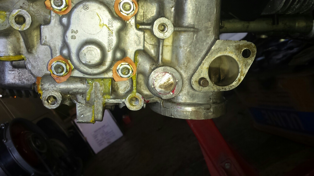
Here’s the early type 4 case
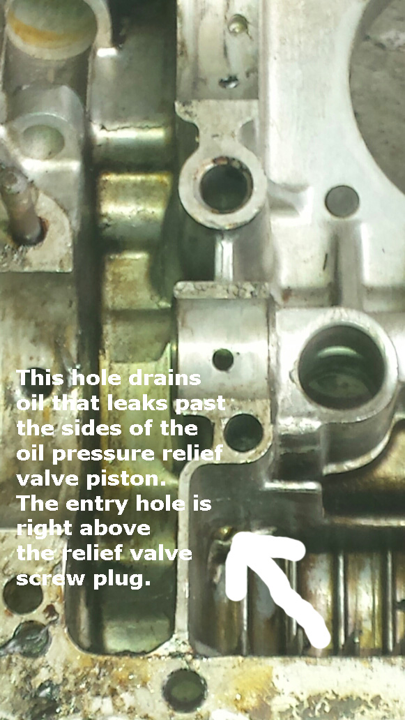
If you perform the repair outlined below, you can drill this hole with the engine assembled and it’s not an option, probably. You’ll need a long drill bit, easily obtainable in many hardware stores. 3/16″ or so. You may find it necessary to remove the pickup tube securing bolt to enable aiming of the drill bit. It’s not critical that it’s in a certain place or a certain size. Just make sure it’s in the galley shown in the above photo. Use grease on the bit to hold onto the cuttings. Don’t sweat it if you get a small amount of cuttings in the engine. The crankshaft is made of steel and many new car bearings are actually made of aluminum. Aluminum is soft, it can’t hurt anything and all bearings are designed (probably not intentionally but by default) to capture foreign material.

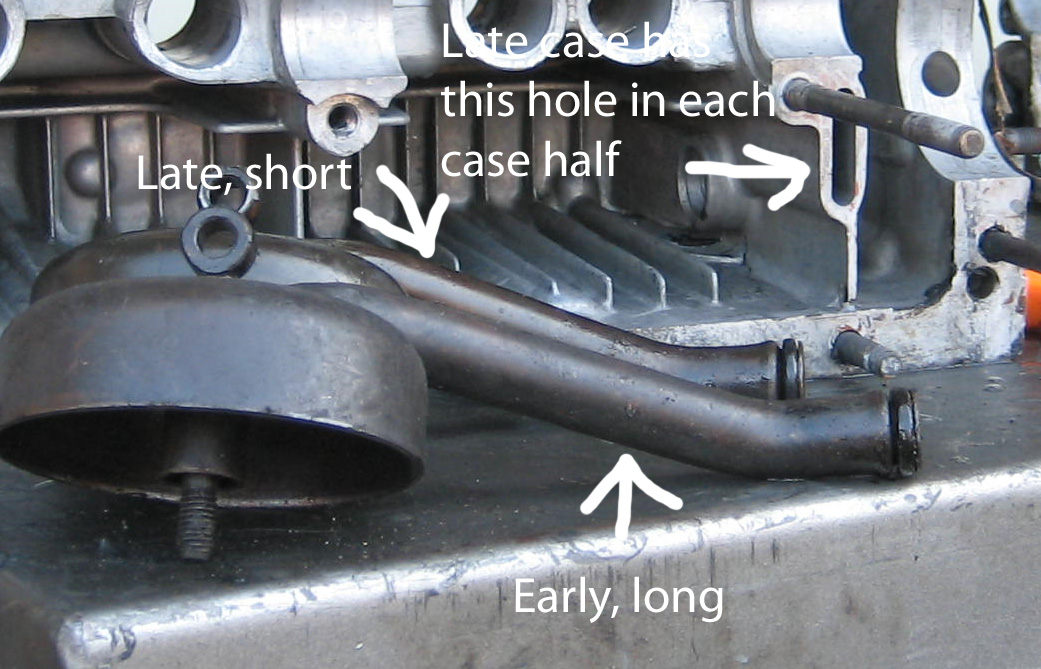
Here’s how the late case is different – water cooled Vanagons have the same thing …
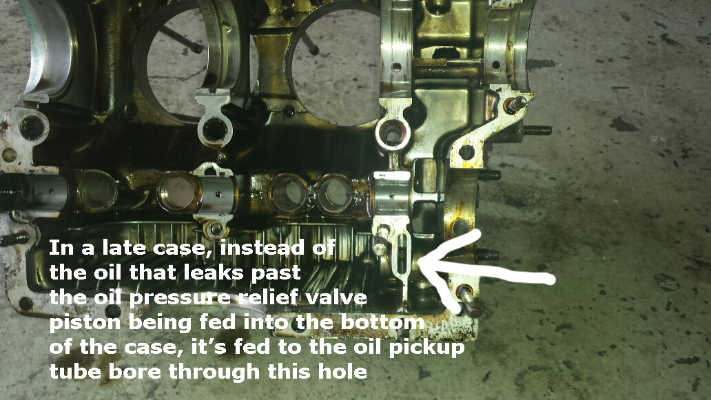
The reason my oil light comes on is because when the vehicle is braking, particularly on a hill, the oil flows to the front of the case. The oil pickup tube picks up oil at the screen and from this hole. If the hole on this side of the case doesn’t mate perfectly with the hole on the other side of the case and since the oil level at the rear of the case is lower when braking, apparently the oil pickup bore picks up air here and not oil as is should. It’s likely that even at higher RPM’s there is the potential for the oil to contain a certain amount of air even though the oil light is out and with a gauge, you probably won’t even be able to tell. A solution to this is to use the early, longer pickup tube. This will block the relief valve inlet hole and you’ll only suck oil. Drill a hole in the galley on the driver’s side of the case to enable draining as in an early case.
You can fix this problem without disassembly. You’ll need to drain the oil and remove the fan housing and some exhaust and you’ll need to remove the plug for the galley (drill a hole in it and pry), and obtain the following …
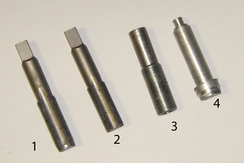
1. This is a 7/8 X 14 SAE tap. You can get this for about 20 bucks. The existing galley hole is nearly the same size as the drill bit required for this tap. Therefore, no drilling is required. Just tap away. Minimum metal will be removed. It’s perfect.
2. Same tap as number one but with the taper ground off. No taper means the insert can go all the way in. This is called
a bottoming tap. First run the tapered tap all the way in, then grind the taper off to finish off the hole.
3. This is the insert. It’s simply a 7/8 X 14 bolt with a hole drilled all the way through. Hole is about the same size as the inlet hole on the oil pump. A little smaller or bigger is ok. Fluid dynamics – hole size is not that big of deal. Just not so big the insert will fail and not so small a bug can’t walk through it. You’ll need a lathe to make this.
4. The larger end of this object will be the galley plug. Turn it on a lathe at the end of long stock, then cut the remnant off. It’s aluminum. It must pound into the galley hole like a nail. Measure the old one but trial fit numerous times until you’re sure the final fit will be right. Before final installation, file the cut threads you’ve created at the plug engagement end galley hole somewhat smooth to allow better engagement of this plug. Use loctite and peen. It won’t leak and it’ll never come out. You’ll need a lathe to make this.
So this is pretty simple. Drain the oil while it’s real hot, remove the pickup tube oil galley plug and tap away. Go slow. The hole has kind of a step deep inside so the tap will resist. Go slow – tap a few degrees, back off, tap again. Use lot’s of WD-40. Removing the tap often and clear out the cuttings to make for minimum resistance. When you finally run the tapered tap all the way in, finish with the bottoming tap. When you’ve got contact with the pickup tube, you’re done tapping. And realized the filter will pick up any cuttings you missed.
Upon installation of the insert, realize the insert will bind. You can’t let this happen. If it gets stuck and doesn’t plug the hole, you’ve accomplished nothing. That’s why the insert you see in the picture is so long – the additional length is a handle so I can run the insert in and out of the hole so test fit. I use lapping compound while screwing it in and out. This erodes the threads in the case so the insert screws in with zero resistance. That’s what you want. After you’re certain this is the case, cut the handle off and you’ve got your prepared insert. Wire brush any burrs formed from cutting to be sure it’ll still go in without any resistance. Clean out the lapping compound with copious amounts of brake cleaner. And realize the filter will pick up any particles of lapping compound that you miss. It’s not gonna jump up onto the crankshaft.
Try to make it so the insert almost touches the tube because if the insert’s not in all the way, the hole won’t be totally blocked. But you don’t want it to actually touch because vibration will cause the insert to wear on the tube (no biggie but they just don’t make car that way). 1 millimeter (remote viewing or just guessing will required) or less clearance is fine. So you make sure the insert can literally screw in easily all the way just by jamming a rather large, wide bladed standard screwdriver into the hole in it’s center and turning it in all the way then backing off a tiny bit for it’s final installation clearance. Don’t slam the screwdriver in too hard or it’ll ovalize the insert and it won’t screw in too easy. If it jams up halfway there you may end up with a headache so think and pay attention. You can even cut couple slots in the end of the insert for easier screwdriver engagement. If you do this, clean up any burrs or the insert may jam. It must be free to move.
Use lots of Loctite for the final, permanent installation. Then damage the threads (technically, that’s called peening) behind the insert so it’s impossible for it to back out. Realize that even though this is potentially an imperfect fix since air may still be pulled in between the the threads or if you don’t think you’ve totally covered the hole, it’s way better than it was before and your oil light will not come on due to this poor design anymore.
This may be effective on Vanagon water cooled engines. And the way I look at it, any case with this original design can only be improved by doing away with this potential for a problem.
Lottsa glue? Prettier than any oil leak which you will have if you go for a pretty new engine today and a leaky oil pump in a few thousand miles. This is the galley plug from the picture above. I cut the end off and pounded it in like a nail. File the surface well so it won’t touch the engine mount bracket. Don’t attempt to use a threaded plug here. There’s not enough material for threads. My oil pump nut gaskets are placed under the washers with sealant and made from the torn off corners of bug generator stand gaskets.
Anyway, if you’re assembling a type 4 engine the late case with the goofy oil system, using the early, longer pickup tube is good insurance. It fits perfectly and blocks the hole. The round came lobe engine got the long pick up tube the first time around.
But I still had to do it twice.
Be careful when fitting the early, long tube in the late, short tube case so as not damage the o ring on the sharp edges of the hole you’re trying to block as you’re inserting it. Use WD-40.
Thing is – you do all of the above, you’ll know what it was like to drive a Volkswagen that works like it did when it was new.
Constantly needing attention? Nah.
It’s not the car, it’s the mechanic(s).
This entry was posted on Friday, September 25th, 2015 at 6:52 am
You can follow any responses to this entry through the RSS 2.0 feed.
