Building an Air-Cooled VW engine, non-Lego Toy Style.
An air cooled VW engine rotates about 150 million times in 30 thousand miles. If that’s too many for you, stop reading. If it’s not, keep reading.
This is how you build a bulletproof, complete, reliable air-cooled Volkswagen engine so when you’re done, you can drive it anywhere you want, as far you want – no funny noises, starts instantly every time, no exhaust leaks, no pushing it outta the way, doesn’t catch fire, no tow trucks, no motel rooms, no pulling the engine in a parking lot to change the clutch (or to try and put the flywheel back on), no oil leaks, no gas leaks, no fumes, no backfiring, nice heater, quiet, it purrs – no nothin’. In other words, it goes anywhere and comes back without a problem. But you can’t skip over anything – if you want success, you need to read it all to understand what you’re doing, why you’re doing it, what works and what makes sense and it’s far from simple straightforward mechanical assembly that you may have been led to believe. I’ll do my best to show you how and it’s all here. And this isn’t step-by-step and you need to read it all, regardless of vehicle to get it all.
Note
If you have a nut anywhere on the exhaust system or anywhere for that matter but particularly at the cylinder head, and you have a nut where it seems it’s so tight you’re afraid it is going to break a stud and it just won’t move, STOP!! The last thing you want to do is break any exhaust stud off in the head. You may never be able to fix it and end up needing a NEW HEAD simply because of one broken stud. So you may end up spending a couple days and a few hundred dollars to put ONE NUT ON. Don’t break a stud!!
So, whenever in doubt, rather than risking a broken stud, heat the nut up red hot with a torch. It will likely come right off. This simple step can you save your hours and hours of work and plenty of $$. Heat can save you a lot of time and money. Usually when something won’t turn, it means something is too tight. Making the respective hole (in the nut) bigger usually solves this problem and heat will do it. This even works on stubborn plugs in carburetors. Just use a real light flame and make sure it’s dry.
Removing the Engine
I’m not going to go into detail here regarding removing the engine. It’s not that hard but here’s the some helpful hints …
If it runs, drive it around and warm it up to thin the oil a bit for draining.
Have a water hose within reach with some kind of on/off nozzle and leave the faucet on or have a fire extinguisher that you know works, regardless of the inspection date on it. Test it first – even if it’s brand new. Water is preferable to a fire extinguisher. Fire retardant is corrosive and makes a real mess. Water is clean and effective. Realize, it’s very easy to drop a wrench in a small pool of gas and cause a spark and start a fire.
Disconnect the battery – a loose wire can cause a spark and thus start a fire.
Drain the oil via the plug if you have one. No reason to remove plate and screen now for this unless you have no drain plug.
Disconnect wires and fuel hoses and plug hoses. Fuel injected vehicles have a hose on each side of the engine.
Type 4 buses and Vanagons have a rather thick wire from the alternator to the starter – don’t forget that one.
Don’t forget the plug to the computer near the battery on fuel injected buses.
Disconnect the shift rod and pull the coupling out of the way on Vanagons and all buses from 1968 and up to prevent damage to the shift rod, the shift rod coupling, and worst case and most possible on a Vanagon – the transmission housing.
Pull accelerator cable completely away from engine and tuck it somewhere underneath to keep it outta the way.
For type 4 buses, remove the entire exhaust system before removing the engine but first remove the muffler then unbolt the passenger or driver’s side header from it’s flange then remove the entire exhaust in two pieces before you remove the engine. You may need to do this on the other side too but leave the rest of the exhaust in one piece for inspection later. These engines are heavy, wide, and awkward. It’s a lot easier to handle with the exhaust removed and it’s considerably lighter, especially on fuel injected vehicles
For buses from 1972 (type 4 buses) …
the first securing hardware you need to remove are are the two bolts that the transmission hangs from – right above the bell housing and right in front of the engine. When re-installing the engine, put these bolts back in right after you attach the 4 bolts that hold the rear hangar to the frame and after the engine is bolted to the trans. Do not unbolt the brackets from the frame for the rear crossmember as it says in the Bentley book, unbolt the bolts that hold the crossmember to these brackets. These bolts are oriented horizontally.
You may want to remove the bumper on any bus older than 72.
Aside from that, it’s pretty easy.
Taking it Apart
Take the flywheel off first with the clutch. It’s easiest to do it right away when the engine is still heavy to resist your effort on the long breaker bar you’re going to need unless you have access to an impact wrench.
When taking off the heads, particularly on type 4 engines, you may find the upper head nuts so tight that when attempting to turn the nut, the whole stud want’s to come out of the case. Use oxy-acetylene and heat the nuts – they’ll likely come off. A butane torch may work or at least help.
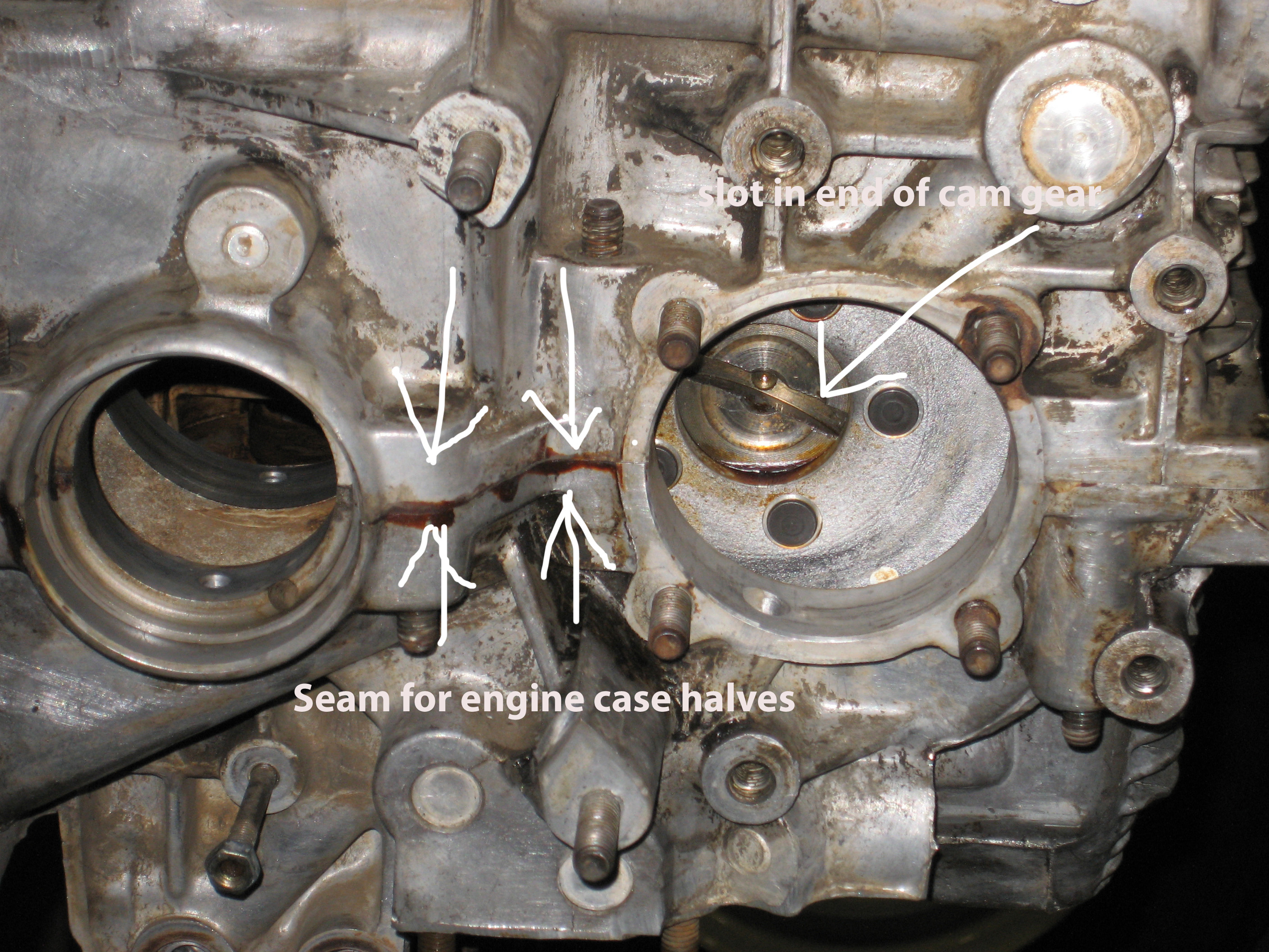
When disassembling the case, make sure you don’t miss any nuts because they’re so covered with glop you can’t see them. The two studs that pinch the front cam bearings and cam plug on type 1 engines are often covered and if you miss them and try to force the case halve apart, you can break the case and you’ll need to find another one.
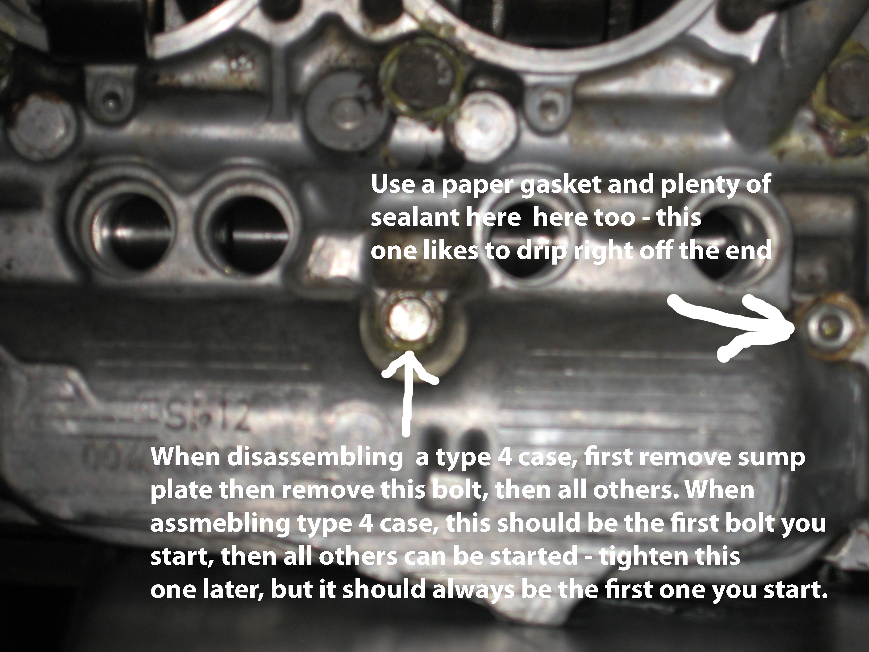
For type 4 engines, never remove this bolt until you’ve remove the sump plate securing nut. Don’t forget this step or you can break the case:
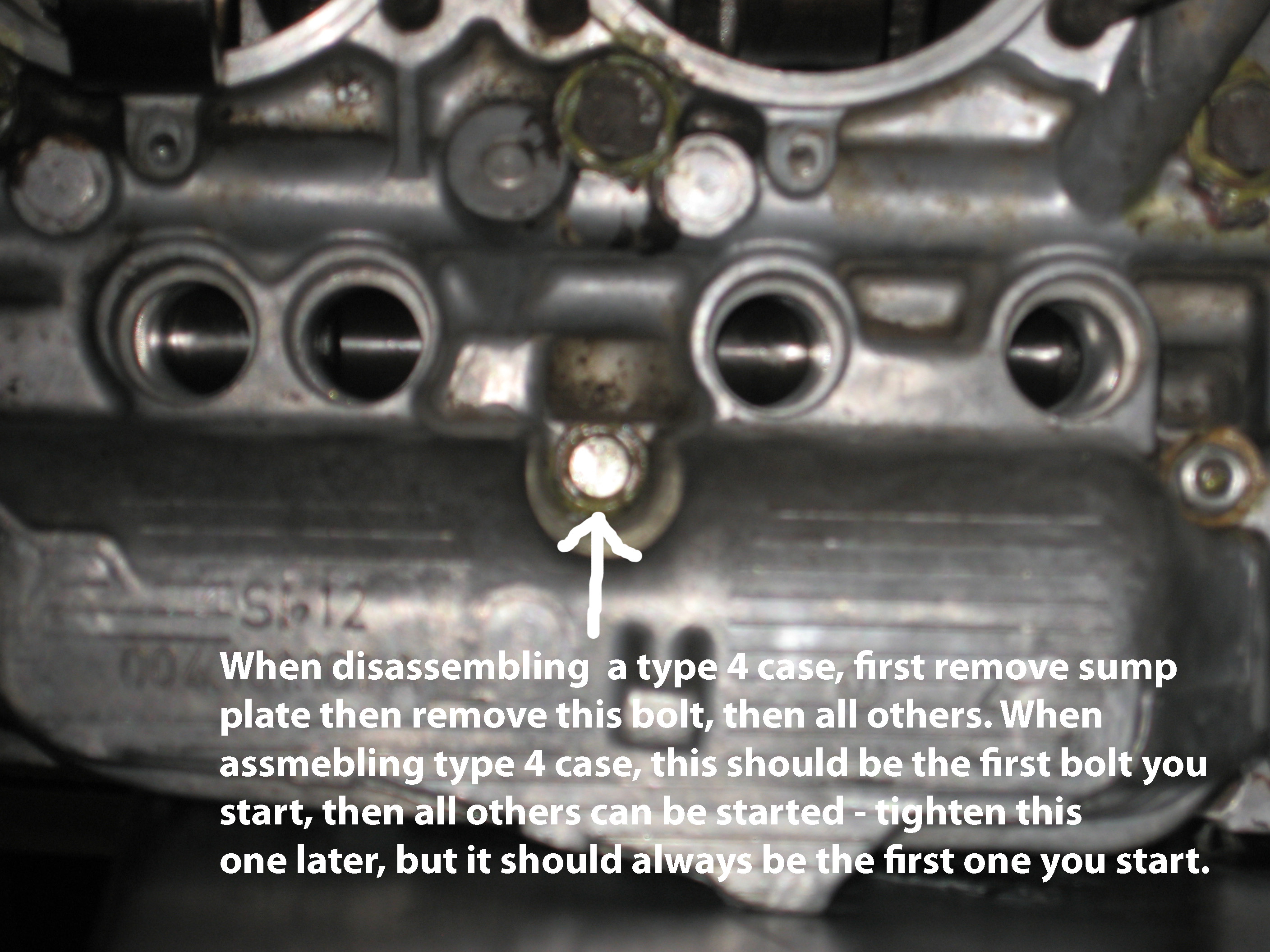
The bolt in the above photo is unique – there’s only one like it in on the whole car. It’s 77 millimeters long including the head and 72 millimeters long not including the head. Thread is 8 x 1.25 millimeters – 8 millimeters in diameter and one complete revolution of threads for each 1.25 millimeters of length (pitch)
.
Notice how the non-threaded part of this bolt is bigger than the threaded part. This wider part is to provide support for the oil pickup tube. Any bolt the with the proper length and proper thread pattern will work but this is the right bolt …
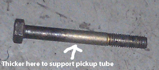
If you do not have this bolt, it’s best to try and find a used one. Thing is, there’s only one per bus on this planet. If you can’t find one, try to find a used bolt that is the correct length that was installed at some time in the past on a vehicle as new or from any new car dealer. Most likely, a dealer will sell you a bolt sourced from the factory and it won’t be junk. If you just buy a bolt at Home Depot (junk) or Fastenal (junk) or anywhere like that, it’ll be Chinese and real soft and will bend easily when tightening it and this can break the case. This is not me being anal – this is reality.
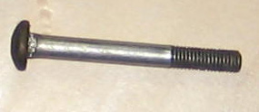 This is the pivot bolt for the alternator for 72 through 79 buses. It’s almost exactly the same dimensions as the proper bolt for the type 4 oil pickup tube. It’s the best thing to use if you don’t have the right bolt for the pickup tube. A bit of creative filing will be necessary but it’s the next best thing to the real thing and it’s a German bolt so you know it’s strong.
Assembly
The starting point here for assembly is the everything is all apart. Clean or not, it can all be evaluated.
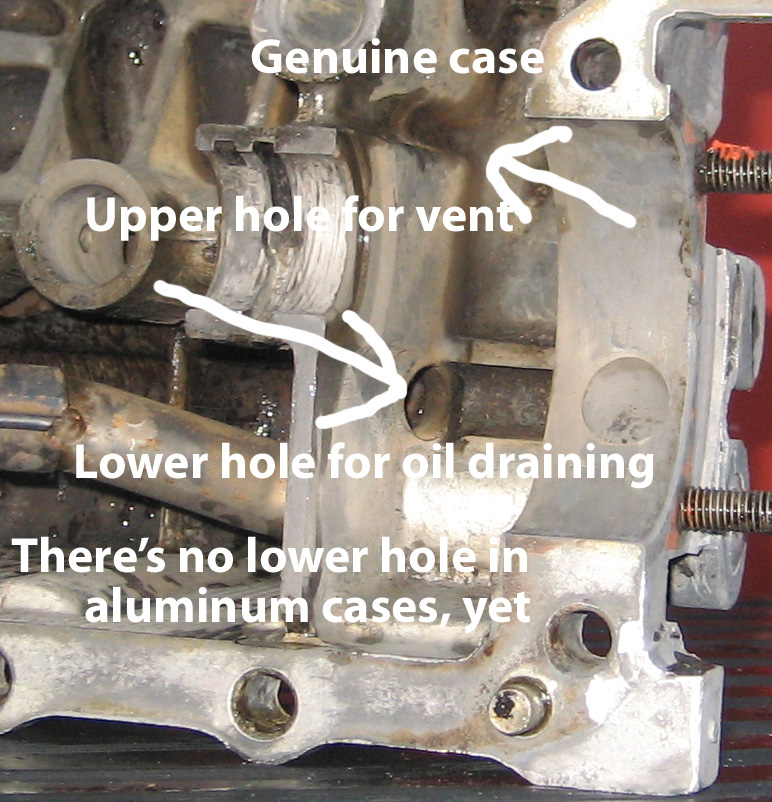
We start with valuable information regarding aftermarket aluminum cases. Here’s a photo of a stock case:
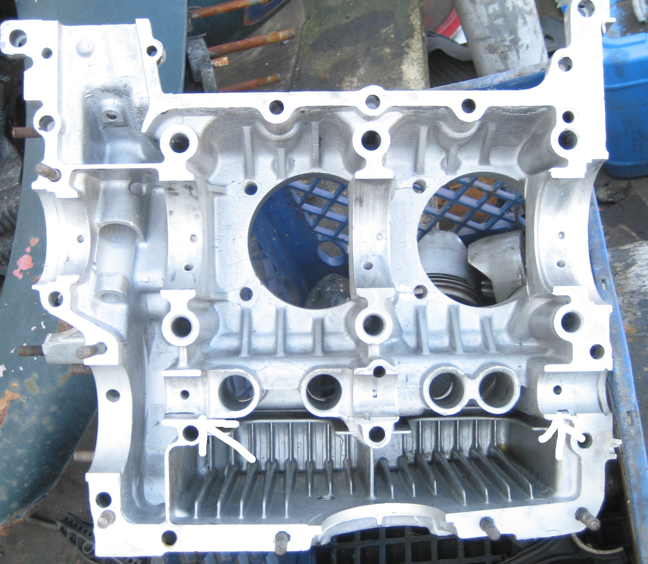
And here’s an aftermarket aluminum case:
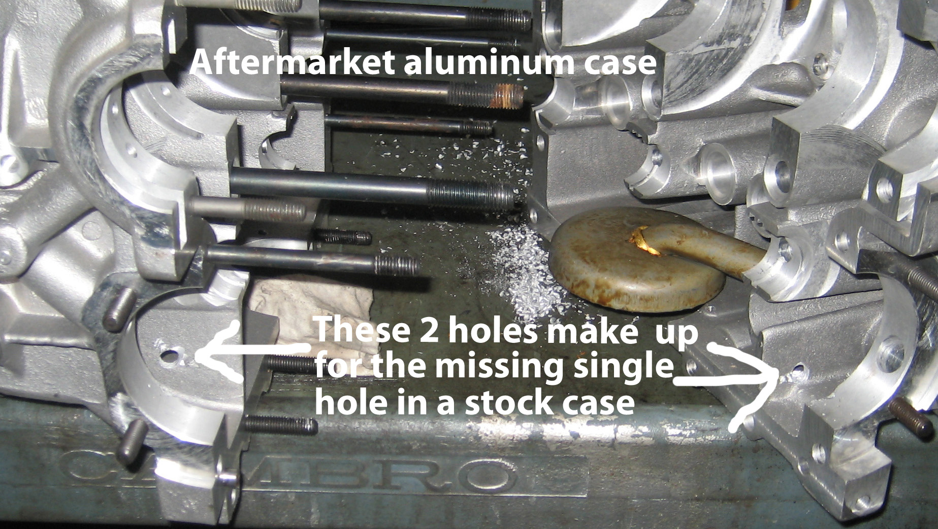
The aluminum case only comes with the vent hole shown in the stock case. There’s no lower drain other than a small slot in the base of the web that divides the crank and cam gear area from the rest of the case. When an aluminum case is assembled without drilling these drain hole, this area has no way to drain other than the small slot and the vent, which is too high for proper drainage. Realize also that the crank gear and the cam gear act like a giant oil pump. Without an upper vent hole and lower drain holes, this area fills with oil and the pressure created by spinning cam and crank gears (just like the oil pump) cause oil to leak past the oil return threads on the crank pulley and even a sand seal will not be an effective repair. If you drill the two holes shown in the picture, you will have no leakage here with either the stock pulley or a sand seal pulley.
Except – you may have a leak with a stock pulley you may have leak develop here over time. To fix you’ll have to use a sand seal and a sand seal pulley to match. There’s two ways to fix this – with a seal designed to install without machining and one that requires machining. The no-machine type of seal can begin rotating in the bore over time but I’ve gone 40,000 miles with one of these and no problem with spinning. But with this configuration, a spacer is needed behind the pulley to make the pulley stick out from the case far enough to clear the seal. Since the pulled hub is very thin walled to accommodate the seal, it always looked like it might break. The machining necessary type seal allows the pulley to have more crankshaft within the hub since it doesn’t require a spacer and thus has more crank within it instead of empty hub.
This machining can be accomplished without disassembling the engine (you can do it in the car) but you’ll need a cutter – about $150. The pulley can be found many places online and the pulley comes in kit form, with the seal. All seals that come with these kits have no spring. Many seals for many applications have a spring – front grease seals, rear axle seals, the nose cone/hockey stick seal on the trans – every one of these seals has a spring. The spring keeps the seal lips tight against the thing they seal against. And technically, the no-spring seal that comes with all sand seal kit’s is really the wrong one for the application. It’s not meant for the rpm the pulley develops. Realize this seal requires machining of the case for installation. It’s the same in every other respect as the seals that come with the kits so it works with your machined hole and with your pulley.
Note – Gene Berg offers the seal with spring as standard. They sell the cutter (periodically – they make them and the sell out quick). For best results use the Berg pulley and hub assembly when you opt for the sand seal. It’s all steel, not aluminum. Realize that in order to use a seal, the hub on the seal must be smaller than stock. This results in a rather thin wall and can break. Happened to me. Started off with quickie, no machine seal. About 400 thousand miless later, the case was cut. The case was cut for the maching type seal. Spacer was removed since no longer necessary so pulley was pushed onto crank farther – maximum depth, maximum engagement with hub. It broke about 500 miles later. Needless to say, this was rather unexpected at best and in reality, very, very, very, very, very, very, very, inconvenient. It also very inconvenient.
You may think it’s insane to drill a couple holes in a brand new case. Well, in case you haven’t noticed, almost EVERY SINGLE AFTERMARKET PART, no matter what it is and now matter what it’s for – from door panels to engine cases – has something wrong with it. So if you want an engine that doesn’t leak – drill these holes! And if you are using one of these aftermarket cases, you’re going to need to use a sand seal and a sand seal pulley. It seems these cases can’t account for the blowby found in a stock case and they tend to leak with a stock hub style pulley sooner or later (sometimes immediately) so you’ll either need to have the case machined for the seal or put one of the quickie, no machining type of seal but sometimes this type of seal can spin in the case so have it machined if you can. If the engine is already assembled or just a running engine, no seal will cure the problem if the holes aren’t drilled in the case. And that’s not the only thing wrong with these cases, besides what’s mentioned in the following. Keep reading. There’s a lot to learn …
The other thing that needs to be done with a new or never align-bored aluminum case is align bore it. The center main is loose on these cases as the come with stock diameter bore. In other words, if you have a new or never align bored but used aluminum case (brand name Auto Linea) you need to align bore it to the first oversize – 0.020″ over or 0.5 millimeters. Without this step, you’ll have lower oil pressure than possible, the crank will be poorly secured, and since the bearing is wiggling, it will eventually begin making noise. It varies, but sometimes it can even sounds kinda like a loose rod.
Evaluating the case, the most expensive part

The back side of bearings differ from brand to brand. Some bearings have the oil groove on the case side, others have it on the crank side. With the oil groove on the crank side, it makes no mark so you’ll have to rely on two things to determine whether you need an align bore – a beaten look on the case bore surface and how the bearing fits into the case. Contrary to the popular belief of some, the ends of the bearing are supposed to stick of past the case a bit. The same is true for the rod bearings. When the case is assembled, the bearings form the proper diameter and a preload is created – a pinching together of the bearing – that keeps if from moving around. It’s gotta be tight; rigid – it’s a car, not a toy.
The same goes for the rod bearings – the bearings are supposed to stick out of the bore a little bit. How much? I don’t need to know. I’d worry if they didn’t stick up.
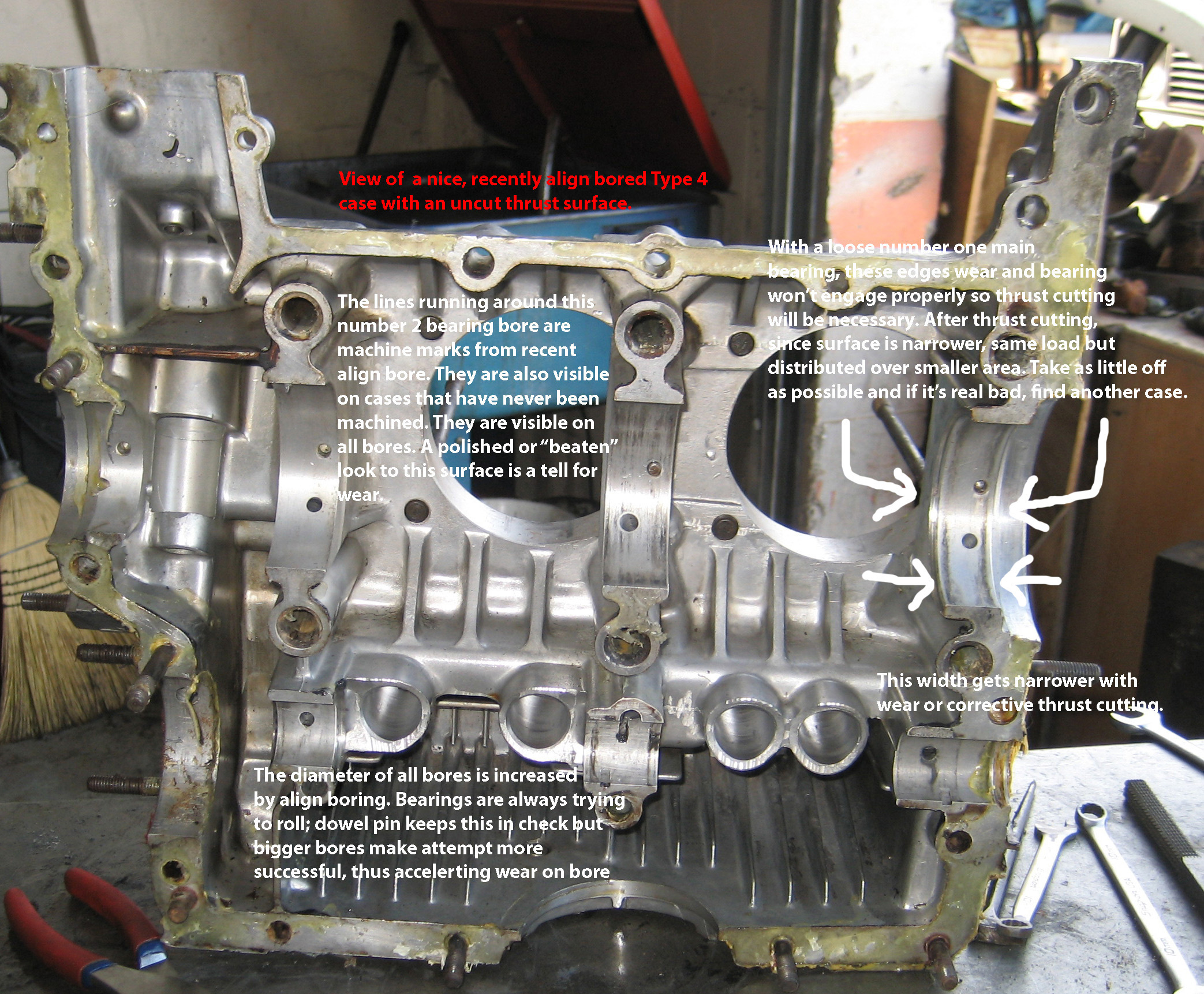
Here’s a crank from a 2 liter air cooled Vanagon engine.
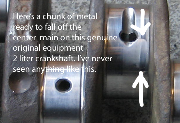
There’s a lotta people out there that think type 4 cases never need an align bore. Hey, everything wears. When the center bearing was put in the case this crank came out of, it wouldn’t even stay in. If one place the bearing half in the bore and case was tuned with the bearing facing the floor, the bearing would fall right out – there was no tension because the bore was bigger than the bearing. This should not happen – this center bearing should pinch when installed and the pinch keeps it tight. The looseness in this case caused the crank to bang around a lot and this constant pounding shattered this crank into submission. When I first saw this, I thought the defining marks were water stains. A bit of polishing and it was still there. I could feel it with my fingernail.
36 hp engines from fifties would sometimes break crankshafts. Since the broke across the cheeks of the crank, the car would still run on 4 cylinders – for many miles. I’ve seen one run for over a year like this. But if this Vanagon crank would’ve broken in the vehicle, since it’s right in the middle, it would’ve stopped immediately. Look close at all the parts in the engine. This problem could’ve gotten past a machinist polishing the crank for you and would’ve left you scratching your head a few weeks after assembly wondering why it happened.
Align boring keeps the bearings secured and thus keeps the crank secured on a fixed axis. A worn case, specifically on the center main, allows the crank to flex and can cause breakage and apparently fracturing. So the answer to the question is type 4 cases DO NEED ALIGN BORING when they align boring or else!!
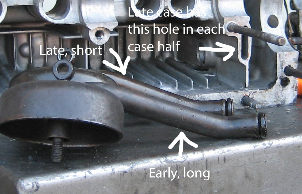
Type 4 Case Oiling
There’s basically two kinds of pickup tube and thus, 2 kinds of cases. The case in the photo had the wrong (long) pickup tube.

Pistons and cylinders
If your pistons are German, this matters –
Measure the clearance between the ring and the piston. You’re measuring ring land play. If it’s less than .005″, use the pistons and cylinders again. Forget all that stuff in the book – this is what matters. Buy new Hastings rings, clean the carbon out of the bottom of the ring land (use a broken ring or a ring groove (land) cleaner). Just clean the bottom of the groove. Hone the cylinders and put it together. It’s not out of the question for a high mileage engine with original pistons and cylinders to be usable. Brazilian pistons with 20,000 miles on them are usually way beyond usable. Chinese? I don’t yet. Don’t toss a German piston until you check. They’re high quality parts. And honing the cylinder makes it a teensy bit bigger – engine will rev quicker.
Evaluating the cylinder heads – click this link …
http://haysvwrepair.com/definition-of-a-rebuilt-head/
More on the case – inserts in the type 1 case based engine …
You need inserts if you don’t have them. Originally up to about 1972, maybe earlier, type 1 VW head studs were 10 mm in diameter and screwed into the case with an interference fit. This means the hole the stud screws into is tiny bit smaller than the diameter of the threaded end of the stud itself thus the hole offers resistance when the stud is screwed in and is supposed to keep it from ever coming out or stripping. This worked fine until VW increased the displacement to 1500 cc’s. The bigger displacement results in a bigger explosion and the increased stress on the studs resulted in stripping. If you don’t have inserts, you must install them. It’s highly probable at least one bottom stud will eventually pull if none have already. It’s just plain sketchy to not put in inserts in a VW case. But if you don’t have them already, you’re lucky. This is because then you can choose the best ones and the best way to install them. The best ones are called Time-serts although there are other similar ones. Time-serts require a smaller hole to be drilled in the case for installation vs some others that require the drilling away of a lot of metal before tapping the case for an insert and when it comes to drilling holes in places, less is more regarding diameter.
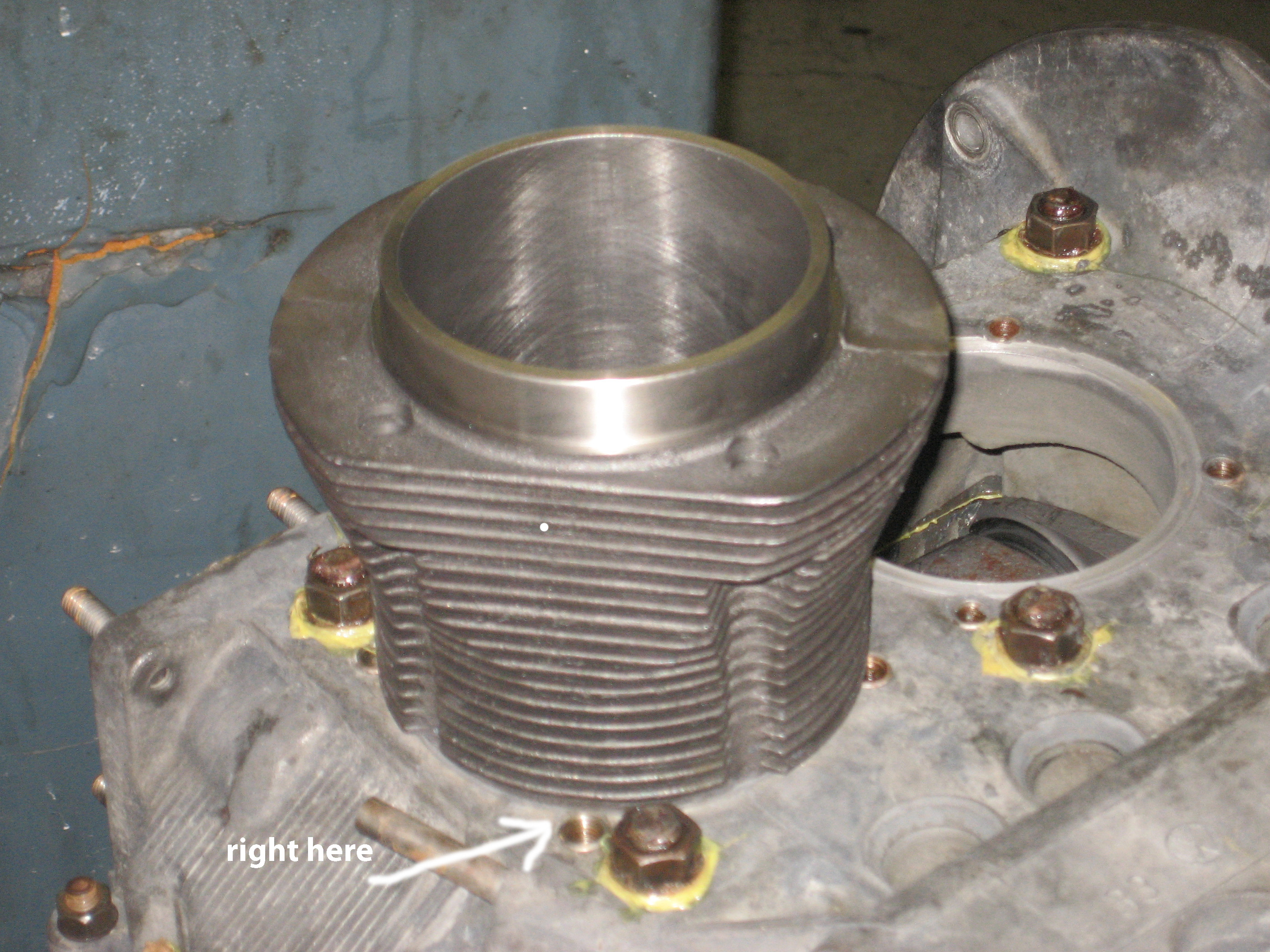
This is what deep studding number 3 exhaust (refer to location) stud is all about …

Non-deep studded cases have the bottom of the stud reach right above where the case tends to crack. The pull on the stud is literally trying to pull the case apart thus weakening it and often causing it to crack. When the stud is deep, he top of the threaded portion of the stud is pushing this area together rather than pulling it apart because it’s on the other side of the weak, crack-prone zone and thus deep studding helps prevent cracking.
But the thing is, there is very little material between the surface in the above photo and the hole the stud screws into regardless of whether it’s deep or not. Therefore, it’s a real bad idea to put an insert here and since it’s the lower, longer stud holes that tend to strip and need inserts and the top stud holes hardly ever strip, there is virtually no reason to put an insert here and putting one in is a bad idea. And if the case is not deep studded and you have it done, you’re putting the stud in virgin material in the first place so it’s not gonna pull anyway and is much more likely to strip with an insert due to the very small distance between the hole enlarged for an insert and the area behind the flywheel and then it will be the insert that strips in the case andyou can’t fix it, even with a “Big-sert”. If you drill the hole for this type of insert, you’ll see side of drill bit showing as it cuts through the case on the flywheel side. And with a “normal” insert here, since the metal is so thin on the flywheel side, it may strip just assembling the engine. It’s happened. Just don’t do it. Drill the hole and tap for the stud, don’t use an insert. How deep? You use a bottom stud for this stud on final assembly. There’s 8 on every engine. The proper hole depth will result in the lower stud protruding from the case the same amount any outer upper stud.
But now you have another issue – if you use the proper tap for the the hole – 10 x 1.5 mm – the stud will wiggle loosely because the hole will be too big. That’s just how “normal” taps are. So what you’ll need is called an interference fit tap. This is a tap a little smaller than a 10 mm diameter tap. You can buy one – Google hard but you can make one by grinding a little bit off of a normal tap using a bench grinder. You can test the tap by turing it it a few turns and checking fit with the stud. Trial fitting and baby steps are required. You should need a wrench to turn it – it should be impossible to turn by hand. Trial fit a couple turns, rinse, repeat until it feels like it’s possible to put the stud in with some but not a lot of force. It it goes in too easy, grind a bit off the tap. After you’ve got the tap dialed in, grind the end off flat creating what’s called a “bottoming tap” so you can tap the to very bottom of the hole and thus the stud will go to the very bottom (back off a quarter turn or so after you hit bottom; use Loctite). By creating the bottoming tap, you won’t have to drill the hole any deeper than it should be as you would to compensate for a tapered hole that causes the stud not go all the way in to your carefully measured and drilled hole.
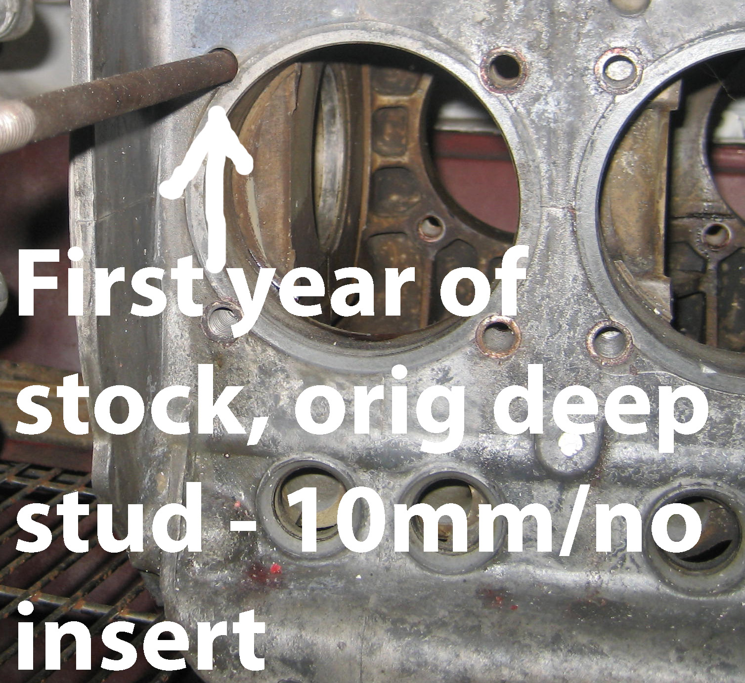
Here’s a stock case from an early seventies bug with 10 mm studs and no insert on the factory interference fit stud. I’m leaving it alone. All other head stud holes have Time-serts installed. If you have this type of case, don’t try to remove this stud unless you really have to. If’ it’s tight, I’d leave it alone. If’ it’s loose ….
Because the Time-sert countersinking tool has to counter sink two surfaces …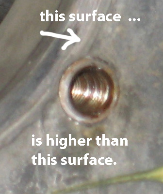
and it won’t countersink correctly so the insert will stick up too high upon installation, and interfere with the bottom of the cylinder …
This condition causes leaks. If your inserts do stick up and touch the bottom of the cylinder (trial fit to check), you’re gonna need a file.
So you’ll need to grind most of the flange off the top of the insert for proper, flush, no interference installation …
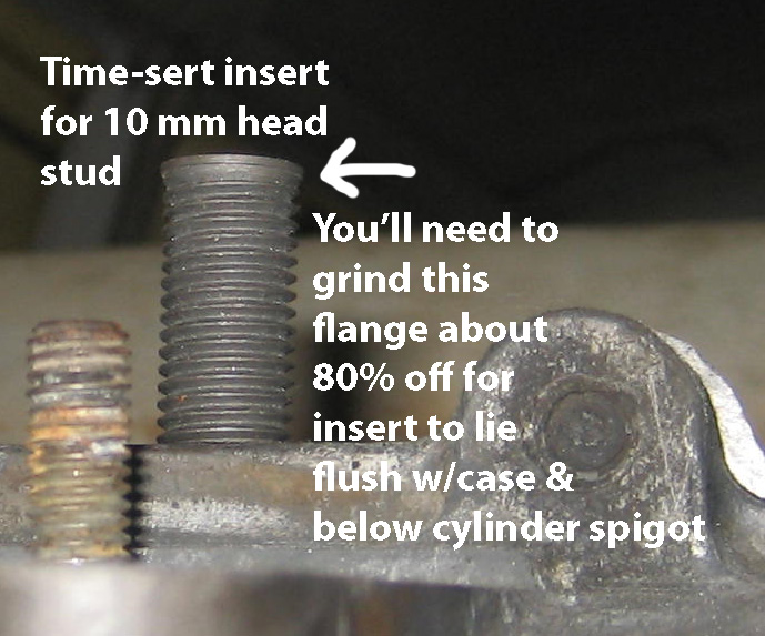
Don’t grind the entire flange off. Some needs to remain so the insert stops screwing into the hole when it reaches this end.
Preamble to Understanding that will lead to Proper Assembly
To understand how the VW engine goes together, we’ll start with the bearings. Bearings are made of several laminated layers although now we’re beginning to see them made entirely of aluminum. But typically, it’s lead on top, then copper, then steel and maybe there’s some aluminum in there too. Lead is very soft. When you bolt the case together, the bearings are in “some” position relative to the crank. When the engine is running, the rotation of the crank literally wears the bearings into the perfect shape the crank demands. This may sound crazy, but I read this long ago in technical article about automobile bearings. As this wearing in occurs, friction decreases and the crank spins much freer than when it was first installed.
So basically, the final machine work is done by the engine itself.
Now the case …
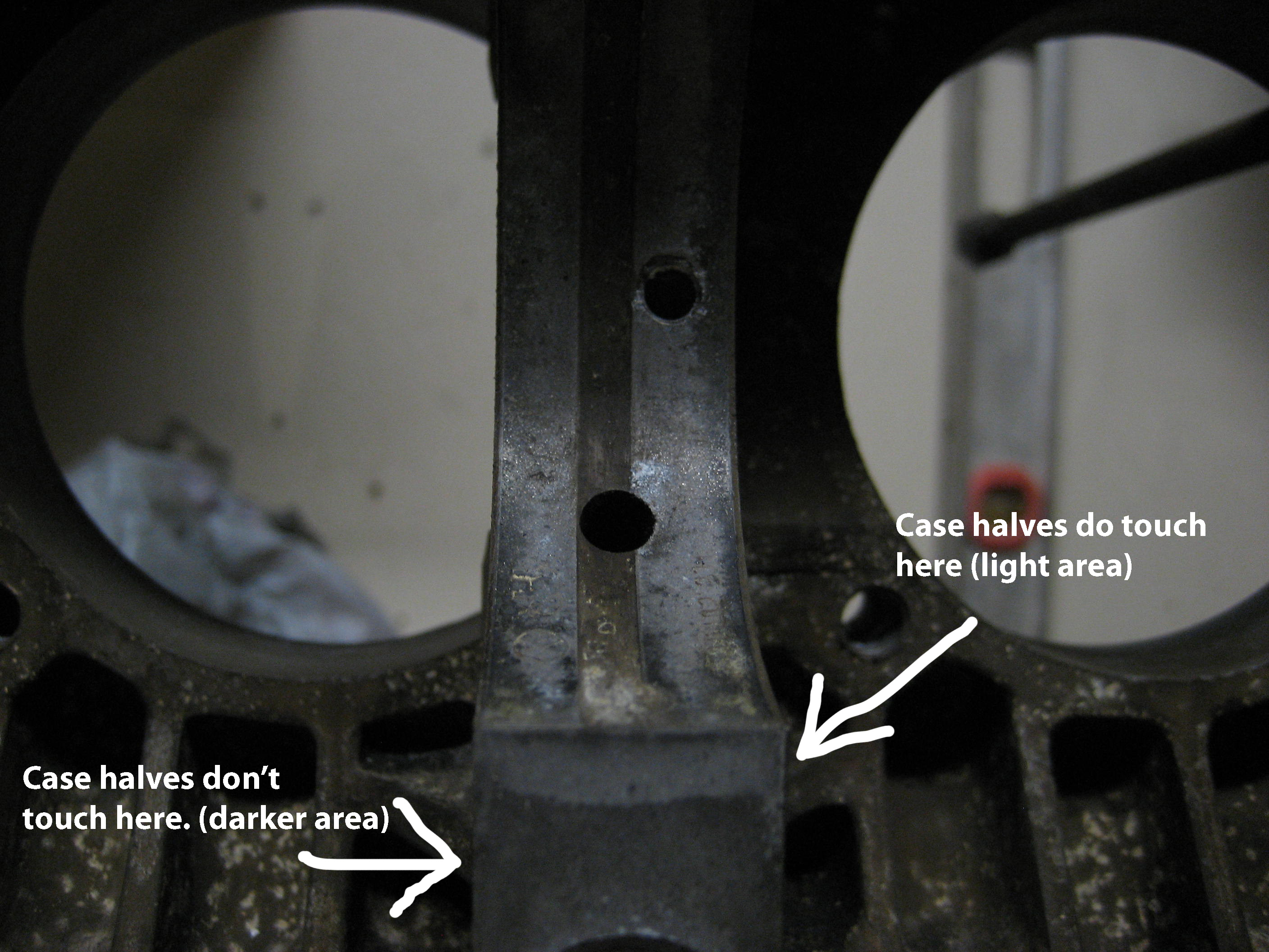
Think of the case as if it’s made of wood. There’s a lot of discussion about slipping a feeler gauge between the case halves at the split bearing. If the gauge goes through it with the case torqued to specs, you need a new case. There’s no specific feeler gauge size to check this – basically, you want both sides to touch. That’s the key to this – they have to touch. If there was a gap and the case was made of wood, you’d just tighten it a little more and the gap would go away. The gap can be found where it states the case halves do touch in the photo. Incidentally, I was the first one who’s ever taken this case apart. VW put it together and put it in a brand new car long ago. Why don’t the the halves touch everywhere the photo suggests they should?
Now look at this …

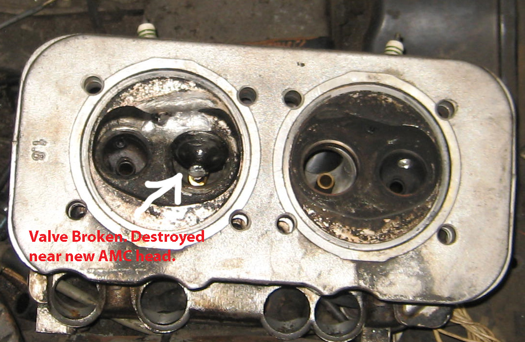
This is a genuine VW head with genuine, totally shot head gaskets (that’s a new one on the right of the photo) head from a 1978 VW bus with a 2 liter engine built by Volkswagens rebuilding program.The sticker on the engine says “Volkswagen of Canada”. Anytime someone bought a rebuilt engine from the dealer, it was built by Volkswagen of Canada. And every single on of these engines did this – leaked copious amounts of combustion by-products and thus a compression leak. Every one. They fell apart. This did happen on engines that had never been apart – built for the car new in Germany – but it seems it took a lot longer. Therefore, I don’t think engines destined for new cars were assembled using torque wrenches, they used something more sophisticated. Perhaps a higher torque, calculated using that particular batch of bolts’ stretch characteristics, perhaps using the amount of stretch for the studs using dynamic testing. And realize, lower head studs are significantly longer than upper head studs so they stretch more upon tightening and thus need a higher torque. After all, it’s always the lower studs’ nuts that you’ll find loosest when re-torque a head on an engine that’s been in service for awhile. The top nuts are usually ok and since they’re not bathed in oil, they tend to get frozen to the stud, especially on type 4 engines, usually requiring heat to remove to prevent the stud from unscrewing from the case. The heads in the photo didn’t “get loose”. The reason for this leakage is because they were never tight in the first place and from the moment this engine was first started, it was beginning to fall apart. This engine had 14,000 miles on it. But an engine built by VW in Germany and inserted into a brand new car usually didn’t look this bad until it had 100,000 miles or more. I’m sure the Canadian rebuilders were using a torque wrench. For new cars, I’m certain it was another method of tightening the heads or a higher torque. Maybe the book values are intentionally low to protect you from yourself (stripped studs)? Who knows. But there’s one thing I’m absolutely sure of – VW engines love to fall apart and the head torque for all 8 millimeter head stud engines is too low and it’s also too low for type 4 engines. For earlier cases with 10 millimeter head studs, the 25 foot pound spec is adequate but it’s better to go higher.
New heads for type 4, made by AMC of Spain – the best thing to use on any type 4 rebuild – do not require the gasket used on original equipment heads. Since there’s no gasket, when you tighten the head, there’s nothing to crush and seal with. Like a mayonnaise jar with nor rubber seal or a faucet with no rubber washer. Pretty obvious with an AMC head, the factory torque is not going to squeeze the aluminum enough for it to meld and seal with the top of the cylinder.
The key thought is this – the cylinder head is the lid to a container where there are often many explosions per minute occurring – it has to be tight and stay tight for real, real long time under the most demanding conditions. Tight heads, more than anything else in the engine is the key to long engine life. VW’s seldom have bottom end problems, at least 90% of all failures are cylinder head related.

Now think of this – think of the studs as if they were guitar strings. If you reach say 20 pounds of torque with all the head studs, as you tighten to 25, you’re going to have to turn the bottom nuts more times around on the stud than the nuts on the top studs because part of the tightening process is also going in to stretching the studs and since the bottom studs are longer, you have to rotate the nut more times after contact with the head to achieve the same final torque as the top studs. You can actually feel the difference in stretching when tightening the heads, just like when you tune a guitar.
Anyway, when you install an AMC head, it has to be tighter than a head with a gasket since there’s no soft gasket to seal – you’re depending on the solid aluminum of the head to meld with the top of the cylinder and it will not happen at 25 foot pounds. Your heads will look just like those in the pictures, or at least on the way there – leakage between the cylinder and the head within 10-20,ooo miles and then, it’s on it way out – lean mixture created by incoming cool air on intake stroke – an air leak.
But you know what happens when you tighten an AMC head or even a genuine head without a gasket to 40 pounds instead of the factory 25? It won’t leak for a real, real, real, real long time. It’ll be dry for many many tens of thousands of miles and that translate into zero air leaks and provided there’s none in the intake system, and the engine was built right in every other aspect and one takes reasonable care of it, the thing that finally takes the engine down will be the pistons – they’ll wear to the point where oil consumption is too high – the rest of the engine will outlast them. So basically, a well-built VW engine of today’s lifetime is determined by the quality of the rings/pistons/cylinder.
Why? Every single new car built for at least the last 60 years at least uses chrome rings – very hard – and hard enough pistons and cylinders to be compatible with them. Today, all brands of pistons for stock replacement have iron rings – much softer than chrome – and pistons and cylinders to match – read “soft”. So what happens is ring lands and rings wear much faster than chrome and eventually excessive oil consumption will become an issue. Perhaps in the form of oil fouled spark plugs. So the defining factor in a well built engine will be the, I hate to say it – cheap iron rings that come with cheap (Brazilian Mahle, Chinese, or anything else for that matter) piston and cylinder kits. So if you want maximum life from your engine, try to find some German Mahle or German Kobenschmidt or Nural brand pistons and cylinders for your rebuild and rebuild it right (and I’ll show you how). But there’s more to just putting them in. You have to prepare them before installation. More on that much later. And you can’t use chrome rings on piston designed for cast iron rings. Pistons and cylinders are too soft to handle it.
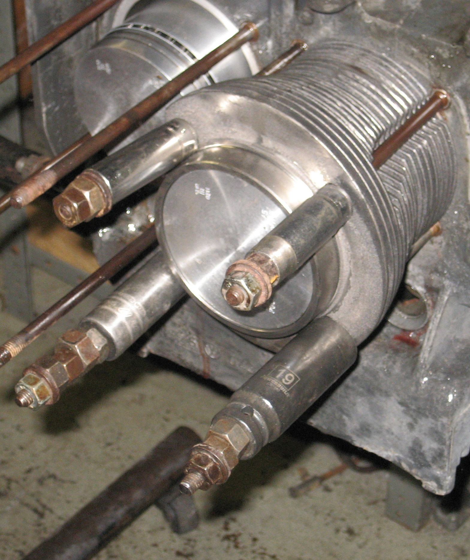
For visual relief, here’s a photo of some automotive rocket science …
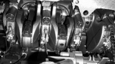
Notice the cables coming off the connecting rods – they’re bearing cap accelerometers.
And a little more …
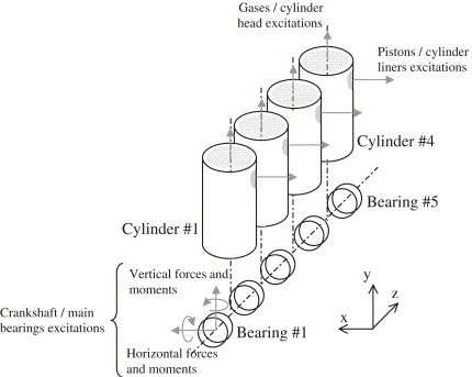
As developed as a crankshaft system is, they’re still trying to improve it. It took a little time but awhile after first seeing this diagram, I began to wonder why the engineers would need to put accelerometers on the connecting rods. After all, they designed the whole engine along with crankshaft and mathematics can answer any inquiry regarding the acceleration of any part in the engine at any speed or position relative to the crank. So why the accelerometers? They’re there to measure bending and flex and any other unwanted or unexpected movement in the rods and crankshaft. A few calculations using engine position can easily determine acceleration in any engine position or speed. Any additional acceleration that’s not included in the math can only be due to flexing and bending of crank, rods, bearings and bearing saddles.
Everything bends. Too much bending, things tend to break. Key to long engine life – the slower you go with regard to engine RPM, the less things bend so the less they break.
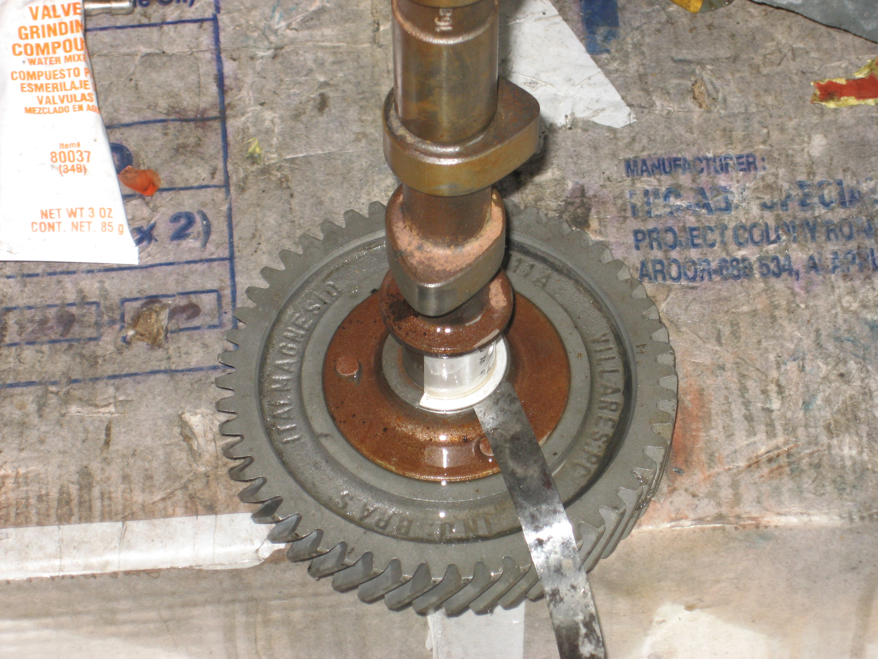
Here’s a crankshaft – it’s got a crack in it …

When this crank was placed in the left case half for final assembly, it had resistance when I tried to turn it. The ’66 bus it was in was running. There was no evidence any kind indicating a breaking crankshaft – it was suffering from …. it was literally falling apart, lotta loose nuts.
The crank turned easily for most of it’s rotation, then it would bind and continuing to rotate, it would begin to rotate freely again. It’s easy to tell. Not only should the crank spin freely, it needs to slide freely from flywheel end to crank pulley end and vise versa.
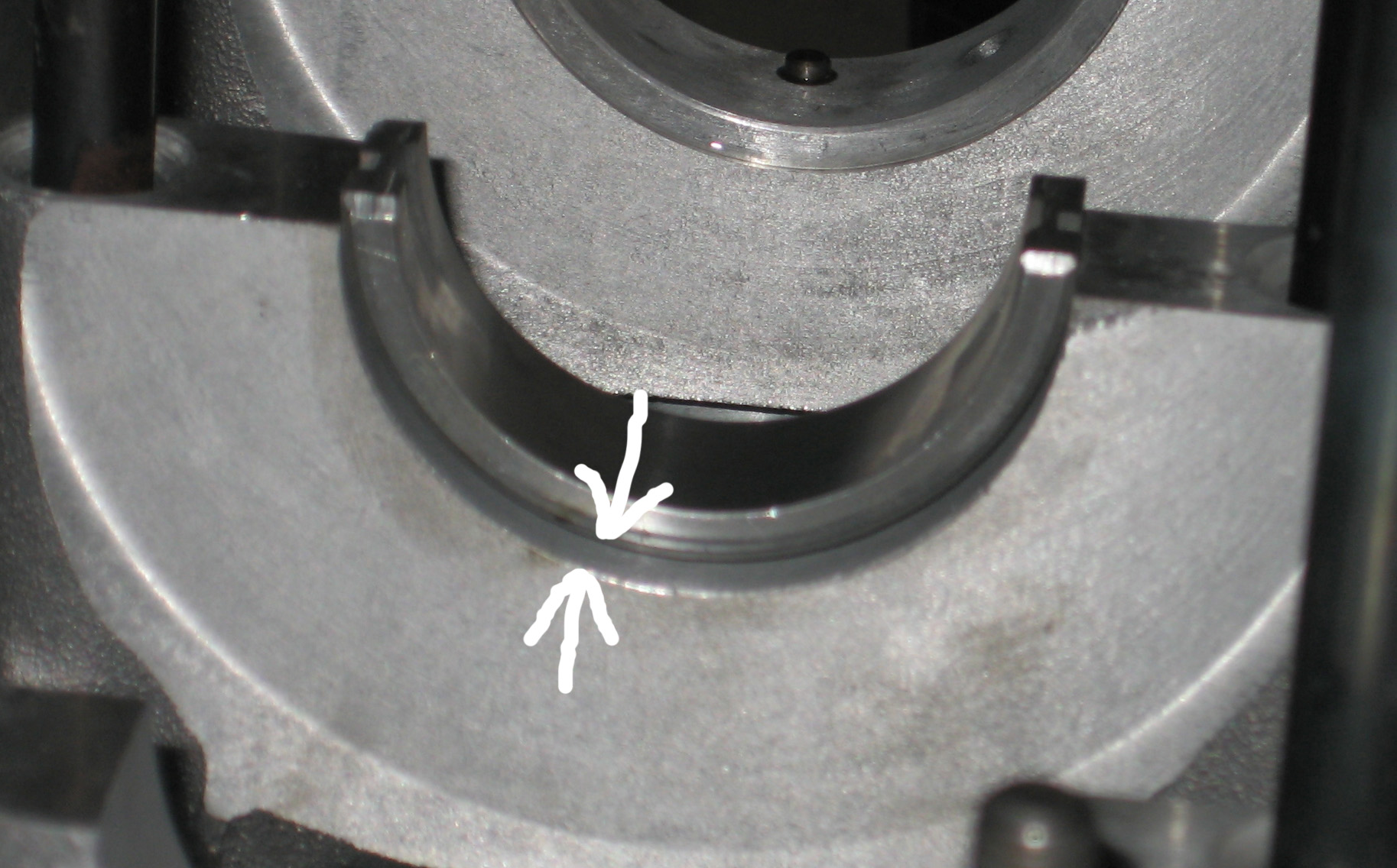
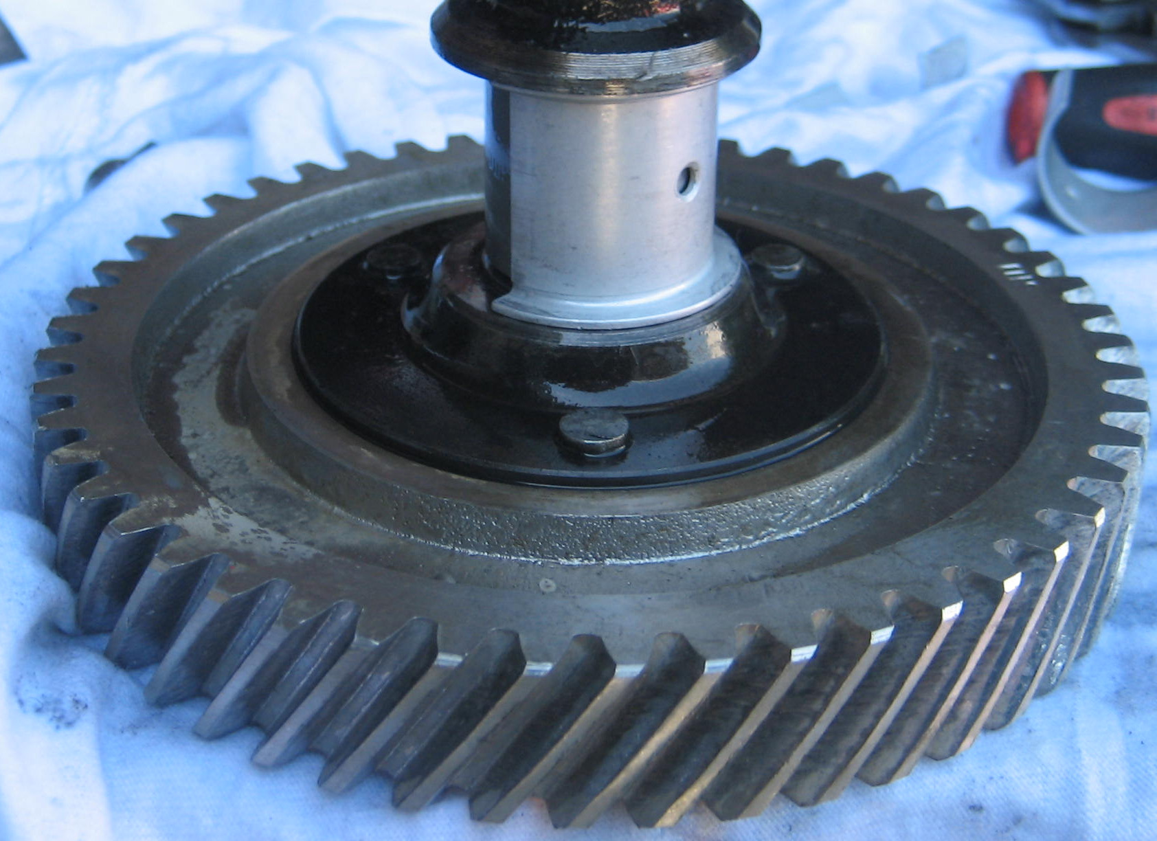
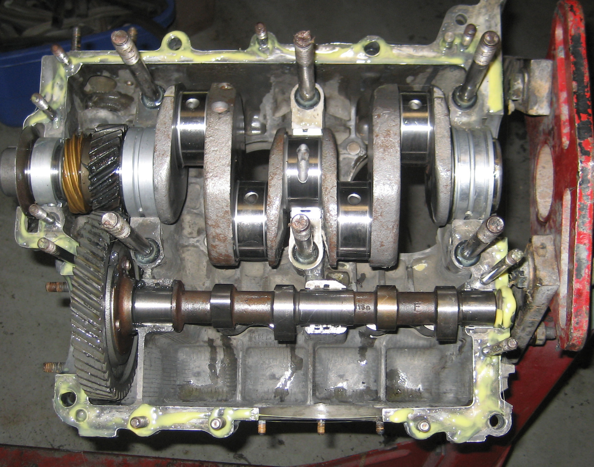
Here’s a Vanagon case with the crank in place for final assembly ….
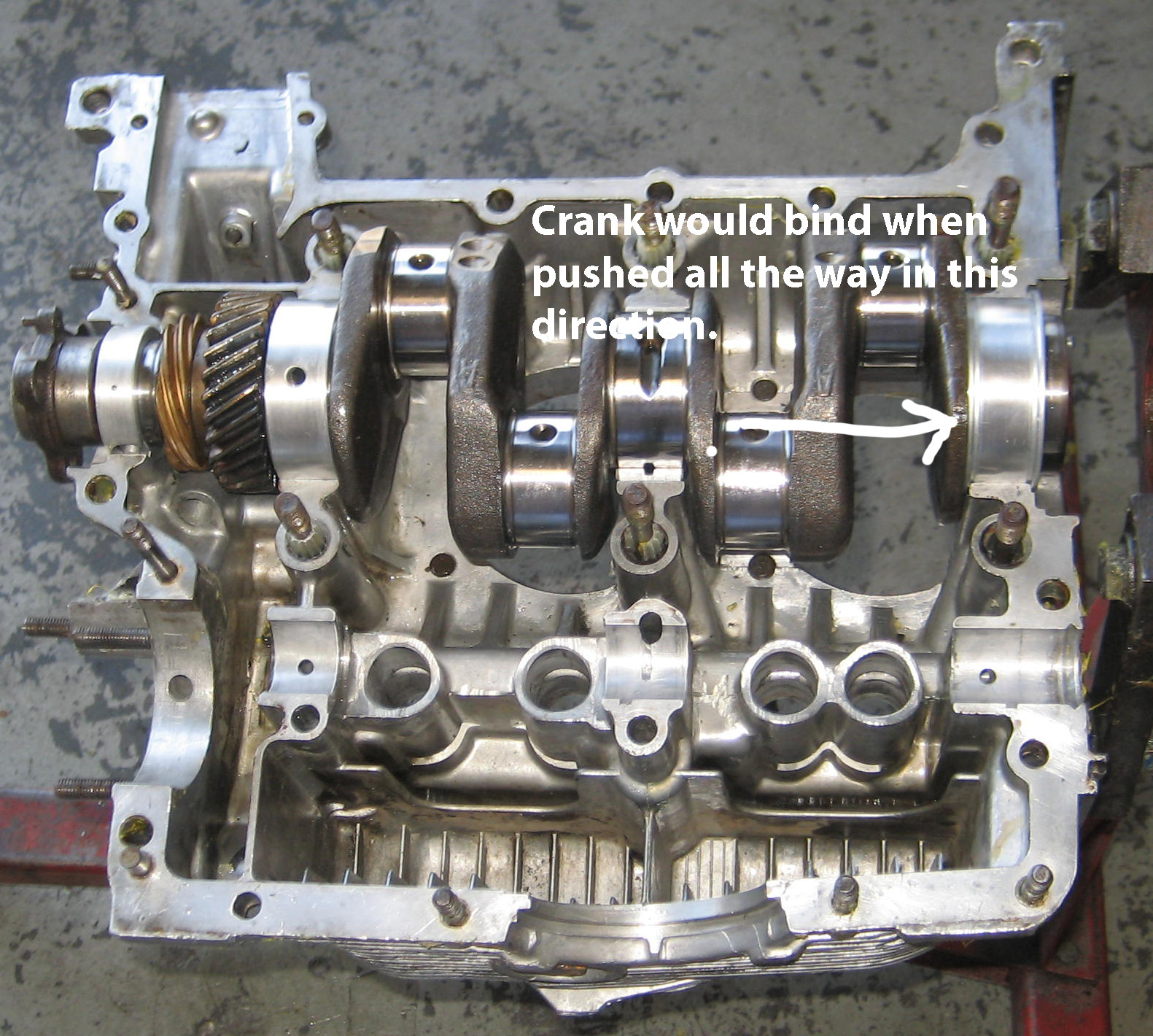
This crank shaft spun freely except when it slid firmly towards the flywheel. In this position, it was binding the full 360 degrees – couldn’t turn it by hand. Everywhere else, it was fine. If it was free when pushed towards the flywheel end, but bound when pushed all the way towards the pulley end, it wouldn’t be a concern. Realize, when the flywheel is on the engine, the crank is pulled towards the flywheel and since there is so little back an forth movement, binding (only when at the extreme, pulley end) is not an issue. And it probably couldn’t happen anyway simply by design.
Solving the problem with the broken crank was not solved by looking for crack. It was solved by realizing there was no other solution. The crack was noticed after the crank was rejected. See how the car tells you what’s wrong with it? Oh, and it was a fake crank. Maybe German Bruck. Not forged. Not genuine VW. Realize, German, for any part, doesn’t necessarily mean quality, it just means place.
Here’s another case of the engine telling us what’s wrong with it. This time, the cam didn’t spin very freely when laying by itself in the driver’s side of the case. Here’s the crack on the passenger side of this otherwise excellent looking (re main bearing bores) type 4 case …

At first thought on might thing this crack is from overtorqueing the pickup tube support bolt. Then why in the cam bore on the right side cracked?
And here’s why the cam didn’t spin real freely when laying in the driver’s side half of the case …
 You can barely see these. They seem to arguably line up with the blunt casting flash on the cam bearing bores and between the lifters. Maybe a flaw from the day it was cast in Germany. This is the only type 4 case I’ve ever seen that was cracked. Sure glad the cam didn’t spin so freely.
One of the steps in solving free movement problems in crank binding is to remove a bearing, check for spin, if still binding, re-install bearing and take out another. You can also look for shiny, polished areas. These are a tell for binding. For the Vanagon engine, I felt the crank was binding on the number one bearing – the one at the flywheel. Seems the chamfer at the edge (corner) of the bearing was interfering with the radius on the crank. Careful sanding with well worn 600 grit sandpaper (or finer) with WD-40 as a lubricant only where I thought the binding was actually occuring was enough to solve the binding problem. How much material did I remove? Exactly one zillionth of an inch. It varies only slightly from case to case (no pun intended).
If this problem was not solved during assembly, it’s very likely this engine would’ve seized the number one bearing to the crank. You may think it’s “wrong” the sand on a bearing, they being so “perfect” and all. Not so. Remember – the engine itself does it’s final machining. But since the end play on the engine is so small, binding would occur when assembled, and with the engine turning as it’s running and metal expansion (bearing gets wider with heat – decreases end play) and no room for oil to exist between the binding surfaces if left alone, and this being a thrust surface when overrunning the engine (opposite of acceleration), the engine would not be capable of of machining itself into perfection and galling would occur and the engine would seize up.
Of course, it might not but do you want to test it or fix it?
Continuing with the preamble …
Cam bearings also present another free movement issue. Thrust surface width varies from brand to brand. Not all Brazilian brands are like this. I elected not use this particular set of Brazilian ones in the pic …
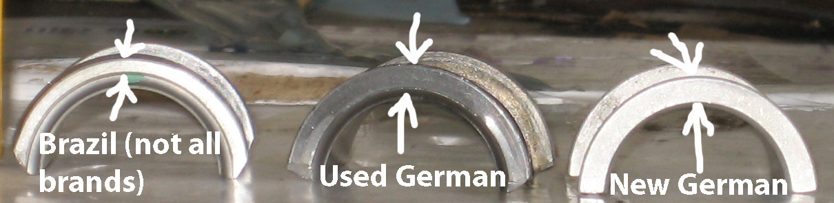
The thrust bearing for the cam must also be checked by placing it on the cam and checking for free movement – this German one wouldn’t even slide on …

The clearance here determines the end play for the cam. The fact that this bearing will not go over the cam is a good thing in that we can literally adjust the end play exactly by book. If the bearing “fell on”, we’d be stuck with that clearance and if too much we’d either have to settle or by another brand of bearings. But this one’s tight …
so I sand a little teensy bit off (just 2 or 3 swipes per side) using well-worn 600 grit wet-or-dry sandpaper flooded with solvent or WD-40 …

And a bay bus back vent glass makes for a perfectly flat
surface for sanding cam bearings and lot’s of other things.
Now trial fit and check for proper clearance …
Repeat until it’s done – just a few swipes of the sandpaper at a time.
If you don’t follow this step and assemble the engine with no clearance here, the bearing will gall on the cam, the galling will fall away, the thrust surface will get thinner, clearance (end play) will be drastically increased, and you may end up with a noisy cam due to it banging back and forth with too much end play. It sounds a lot like someone gargling.
Now here’s some cam bearing debris …
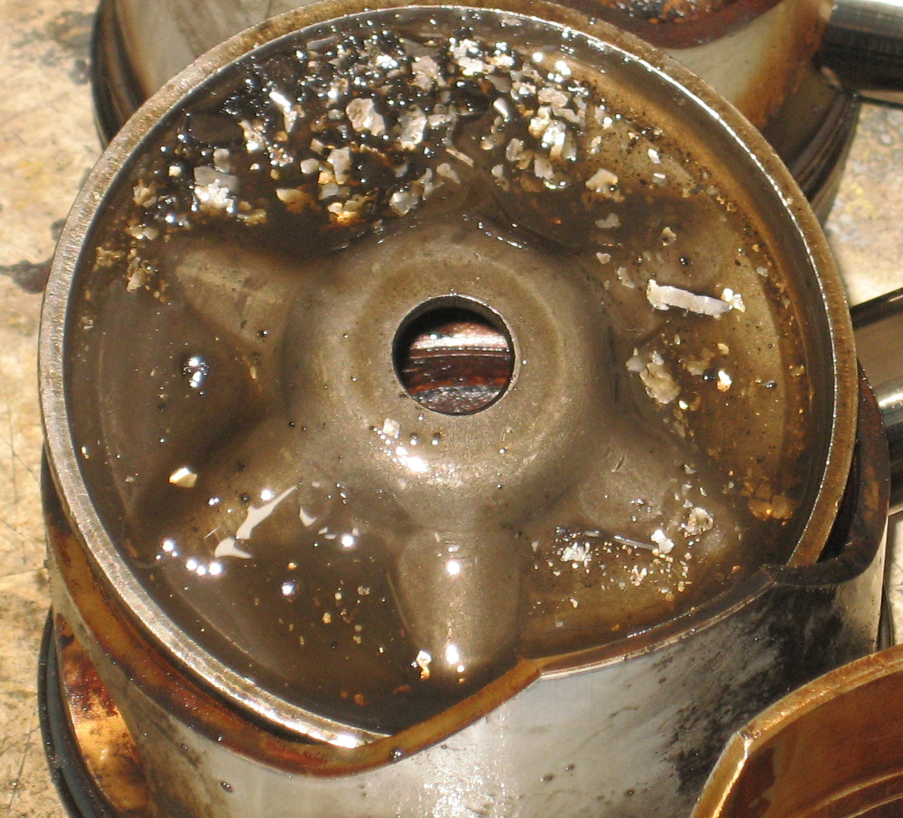
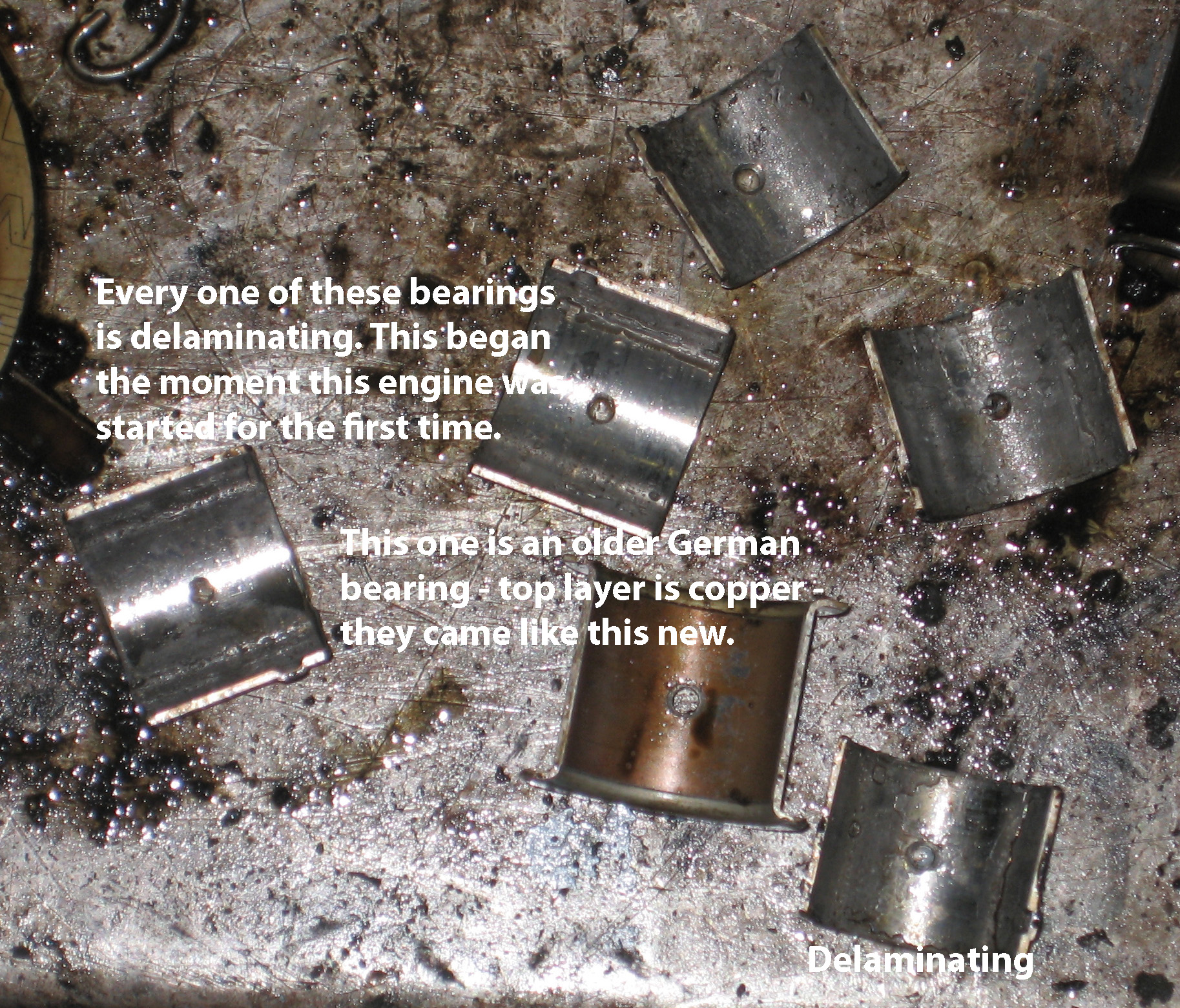
And here are the cam bearings it came from. They’re made of multiple layers like plywood and they’re delaminating …
This is a very common problem on type 4 engines.
The reason these bearings are in this condition is because the engine builder didn’t check for free rotation of the cam. But you can’t check for free movement of the cam simply by laying it in the the engine and rotating – you must partially assemble the case with the cam installed. You only need to use the studs and bolts that surround the cam bearing bores. This engine was rebuilt by Volkswagen of Canada and sold at a dealer. Do your own engine.
With the cam/bearings oiled and installed in the case all by themselves and the nuts tightened that surround the cam bearing bores, rotate the cam with a screwdriver engaged in the oil pump drive slot and see if it turns easily. If it does, great. Take it apart and carry on. If not, take it apart, apply fine lapping compound to the bearing (add a little WD-40 if the lapping compound seems to pasty and keep the lapping compound off the thrust surfaces of the cam and the bearing), reassemble, and rotate exactly 53.76 times with your biggest screwdriver. Disassemble, completely clean the lapping compound away, polish with fine crocus cloth, reassemble only with oil, and check for free movement. I you have it, great – disassemble and carry on. If not … rinse; repeat, until you’ve got free movement. You may have to do this five or ten times. When you finally obtain free movement, polish the bearing surfaces one more time with fine crocus cloth and WD-40 and the bearings are ready for installation. Realize you must not mix up the bearings even if you don’t have to lap them. The cam may not spin freely if you mix them up. And the lapping process makes each bearing especially unique and they must go back in the same place each time including final assembly.
Judging from what’s been shown above, it’s pretty obvious that perfect is hard to come by – at least regarding the soft metal parts of the engine – the case, the heads, and the bearings. In the way that it seems obvious that the heads need a higher torque than the book calls for, think of all of the aluminum parts in the engine as made out of wood – particulary the case. Wood is rigid, but it’s flexible. The joints on woodworking projects firmly”meld together” when tightened. The case halves and the head/cyl/case interface must meld for long life of any air cooled VW engine or it will fall apart. To be succinct, rather than a collection of parts, it must be all one piece.
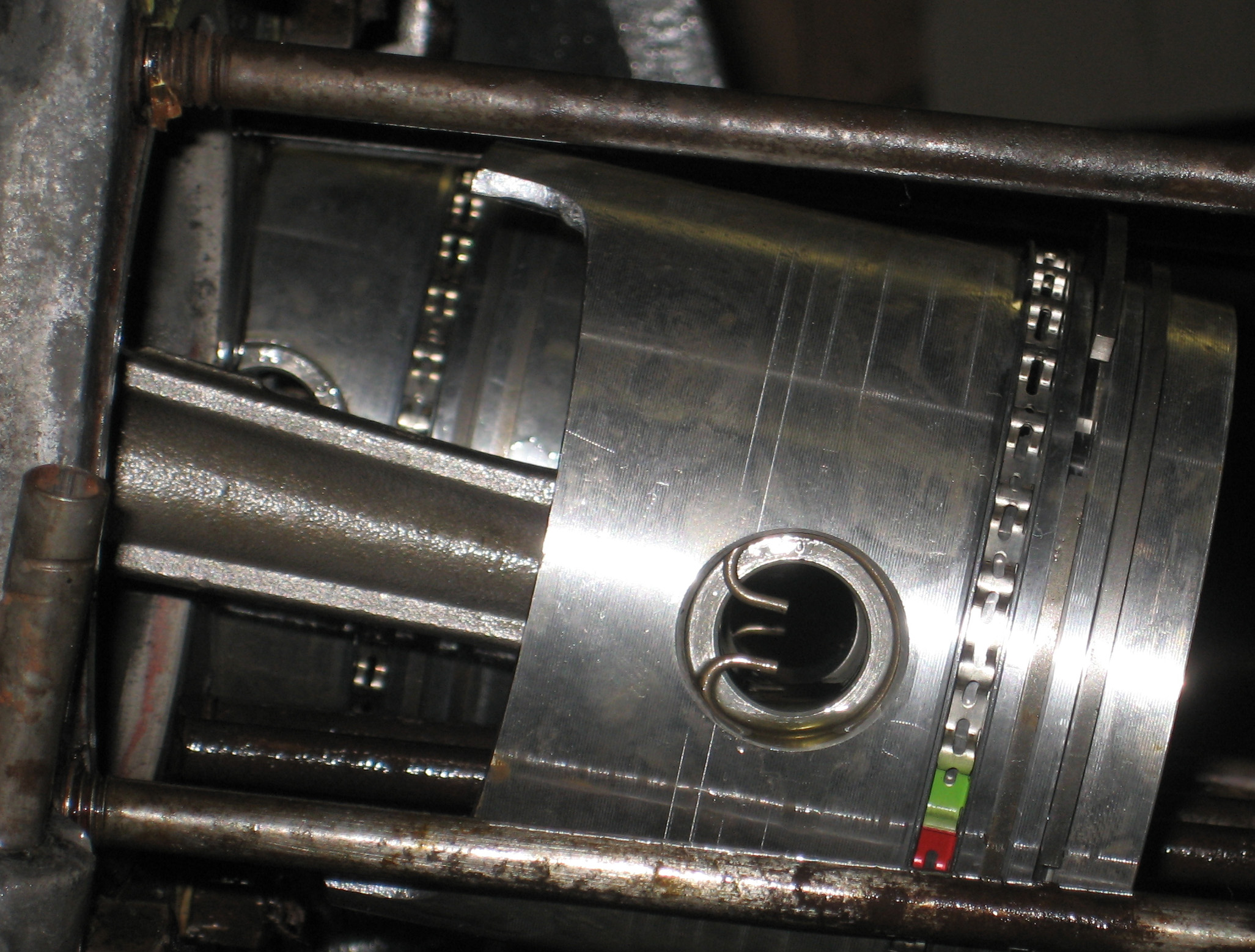
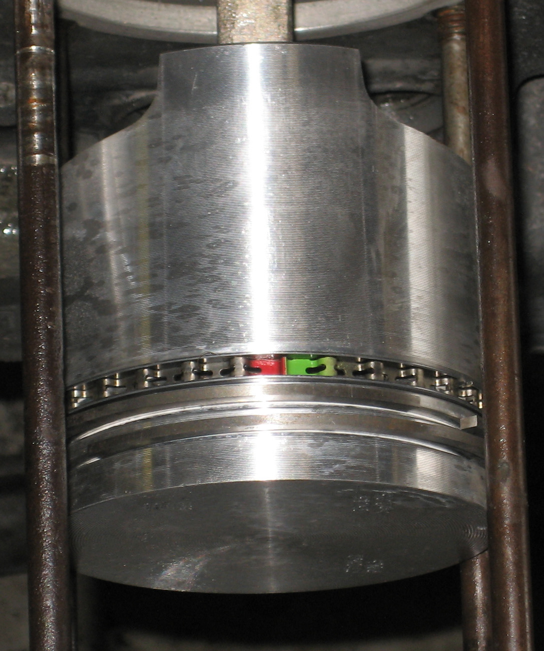
This is what it looks like in reality when it’s all one piece, non – Lego Toy style …

And this is what it looks like on paper – Lego Toy style (also known as the “going through the motions” method), is destined to literally ans slowly fall apart (leakage will begin in many places including between the cylinder and the case and also and more importantly between the heads and the cylinders with a lean mixture cooking the valves and their respective seats thus destroying the sealing between the valves and the seats and damaging the head beyond repair without a seat replacement which, in my opinion, is a not a viable, reliable repair), plagued with small leaks from day one only increasing as time goes on and stinking up the heater, and combustion by-product leakage between the cylinder and the cylinder head – self destructive mode from the first moment it’s first started.
Putting it Together
Seating the bearings allows you to properly evaluate the rotation of the crank ….
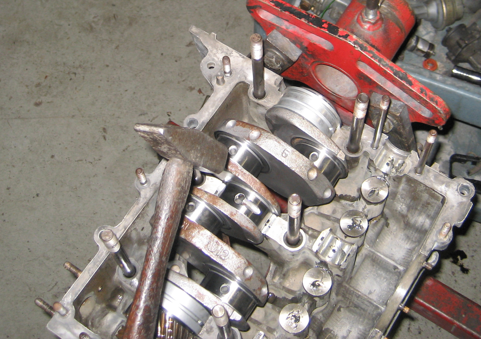
Tapping the cheeks of the crank forces the bearings to seat properly into the case. The crank should rotate freely for a complete revolution with no binding whatsoever – free rotation throughout 360 degrees with no binding.
Now install the cam …
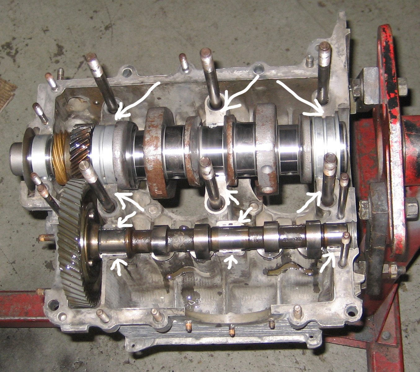
Rotate the crank both clockwise and counterclockwise. The crank should turn freely and when rotating counter-clockwise and the cam should not try to lift from it’s bearings (negative play) and there should be no backlash (play) between the crank gear and the cam gear – according to the book. The thing is, the only way to solve a binding cam or excessive backlash problem is to have the right cam gear. Cam gears come with different “pitch radiuses” which, through fitting different cams, one finds the perfect cam gear which results in no lifting and zero play. To reach this point of cam gear backlash nirvana, you’d need to have several cams on hand and you can’t go by the markings on a used cam to determine which gear you need on a new cam because you old cam gear is worn and is not comparable to a new cam with a new gear. And new type 4 cams do not come with a gear and new gears are pretty much all standard with respect to pitch radius so you have no choice. But the thing is, a little play is no big deal. You gotta use your own judgement.
If your cam is binding in one spot, there’s probably a burr on the crank gear – it’ll wear in since the cam gear is very soft compared to the crank gear. If it binds for the entire revolution, there’s nothing wrong with using lapping compound on the gears and rotating by hand until free movement is obtained and the final result will be zero backlash as required by the book and thus perfect cam gear to crank gear mating. So a binding cam gear combined with the use of lapping compound and a bit of lapping compound leads to perfection. You make think persuading the gears to mate properly with lapping compound is a no-no. I promise, it works – no ill effects, guaranteed.
The main point to take home here is for the crank and cam to spin freely before you assemble the case halves. Ignoring binding now will require, at best. taking case apart again and worst case, can result in damaged main and cam bearings later (copper in the sump plate found during an oil change) or at worst, a seized engine perhaps shortly after you get it running
There’s a myriad of sealant’s to choose from when sealing the case. Here’s just a few …
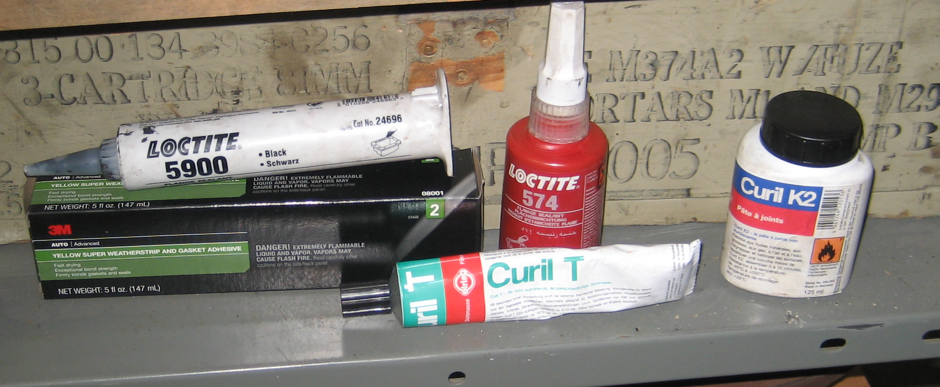
And there’s this – it’s almost like runny rubber cement …
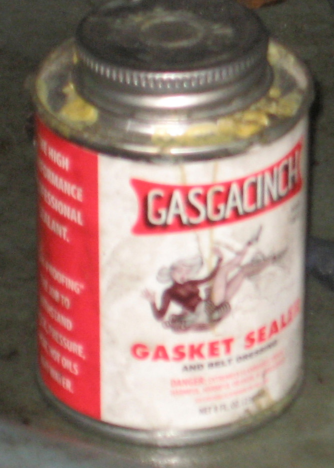
Apply Gaskacinch at all mating surfaces in the case – everywhere the case halves touch. It’s ok if some flows behind the bearing – it won’t hurt anything. Don’t forget he o rings on type 1 applications …
I use a layer of Gaskacinch on each half of the case and a bead of 3M Weatherstrip adhesive on the driver’s side half and on both sides of the cam plug. You can use any sealant you want – there’s alot of them including some German brands. Whatever you do, stay away from Aviation Form-a-Gasket. Use the Gaskcinch on all mating faces including and add the 3M stuff on the perimeter. And realize, using sealant isn’t just paint the the surfaces – it has to work. This is especially true for the bases of the cylinders – this is a common seep on many recent rebuilds. And it’s a lotta work to make it go away the second time.
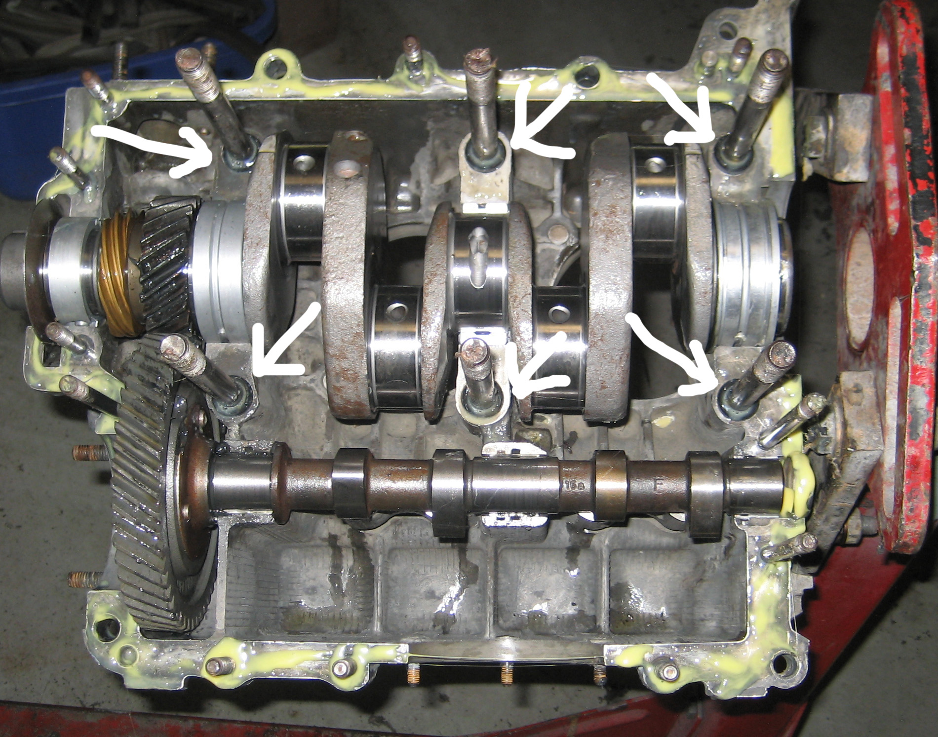
For type 4 engines, you need to insert the case through bolts into the engine and through these …

After the other case half is laid onto the first, snug this bolt first, every time
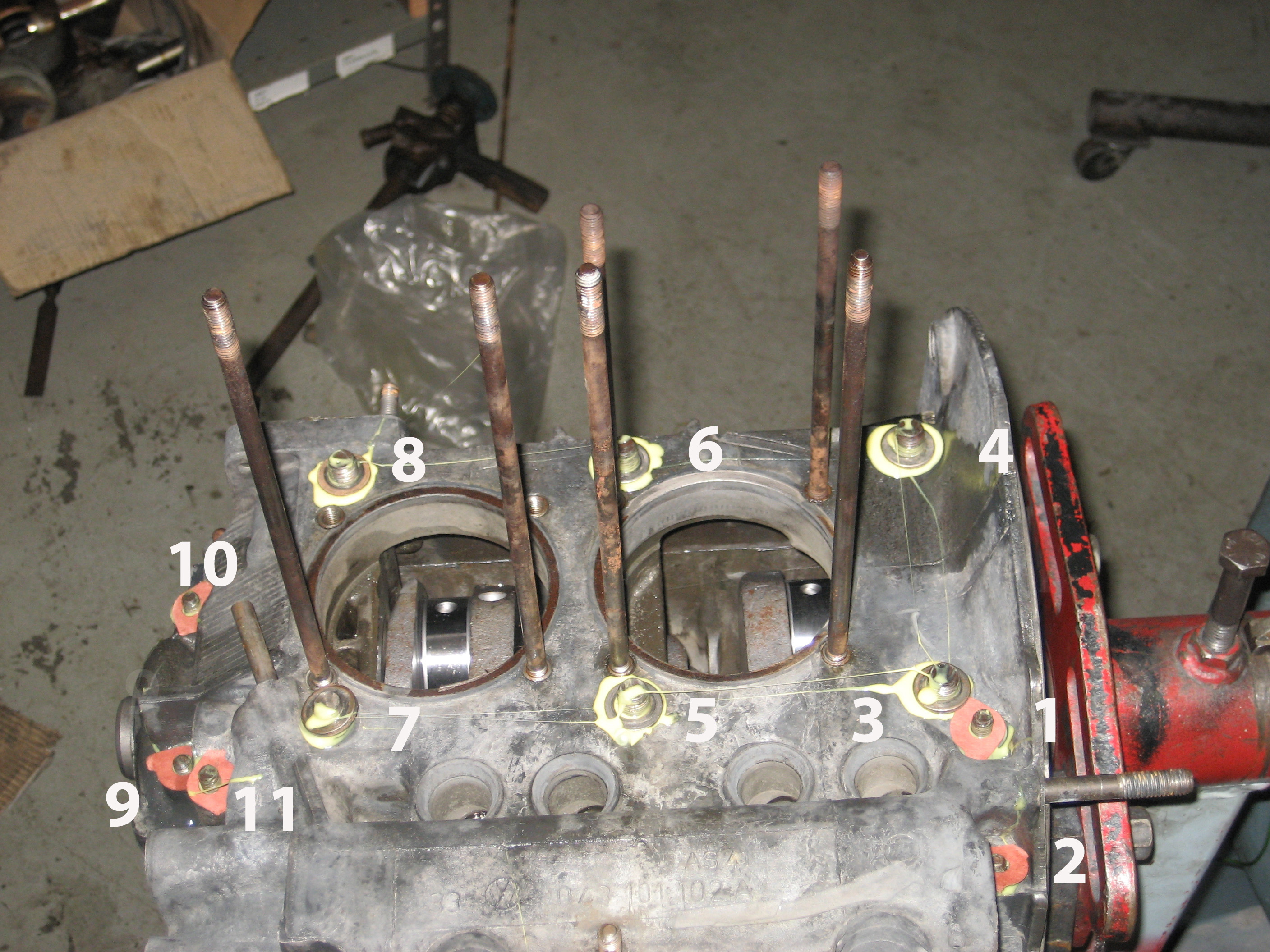
After you put sealant on all the through-bolt washers and threads on type 4’s, push them home with a hammer and put the nuts and washers on the other side of the case and tighten. Us this order for both type 4 and type 1 …
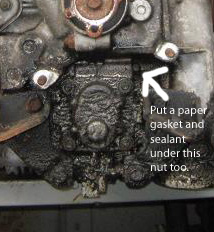
Put paper gaskets and glue under the washers for the oil pump cover too or it will leak. This pertains to all models with the engine in the back including water cooled Vanagon.
This is what happens when you don’t put sealant and paper gaskets on the oil pump studs …
You want to tighten from the origin – from big to small, from opening (bore, sump plate) out or away from. The sealant keeps oil from seeping between the case and the washers and between the threads of the bolt or stud and the threads on the nut. This is very common leak. The paper gaskets in the photo are made from generator pedestal gaskets. This is what the small round paper gaskets that come in a gasket kit are for. There’s 4 in the kit. I need 5. Note the reason for these studs and bolts – they pinch the bores for the crank and cam together and where they screw into the case, there’s the potential for oil pressure to force it’s way out between the stud and the case like both of these on a type 4 case …
I tighten all bolts in VW engine by feel (except for the connecting rods and no, I didn’t forget them, i put them on later. Hope you don’t have really big hands and if you do, a small friend my be of help. I don’t use a torque wrench, haven’t for a long time. You can do the same but I do suggest you disregard the torque specs in the book. For instance, all years had the big nuts on the case torqued to 25 pounds. In 1967, VW decided that sealing nuts with the plastic sealing ring facing towards the case were the key to preventing leakage at these nuts and with the use of these nuts, VW required a torque of 18 pounds. That only lasted a year or two since many these engines quickly and literally fell apart. It wasn’t uncommon to find these case bolts turnable by hand and lot’s of oil leaking from them. Tightening them back up cured most of the leak and … no torque wrench will fit there on an assembled engine and no ill effects – just tight. This is something else.*
*25 today, 18 tomorrow, 25 the day after tomorrow. Engineeering? Que? What?? All for 6 pieces of plastic? Must be some heavy calculations they were using. Or was it something else?
VW went back to using 25 pounds torque and but still using the sealing nuts but with the sealing ring facing away from the case. Use sealant and torque to about 30 to 35 pounds – no sealing nuts required. This is the thing – each stud (or through bolt) goes through a different environment in the case. Some areas have more mass and thus more strength and are less compressible than others. So in reality, each one should have a different torque. If you’re sensitive to it, you can feel the case give more on one stud/bolt than another when it’s tightened. The max here is about 35 pounds. Slip the crank pulley on just far enough to use it to turn the crank as you tighten. If you feel binding (see above, far above, regarding binding issues), loosen a bit and check for free movement. If you you’ve hit 35 and feel binding and just backing off a little relieves the binding and you’re still around 30 pounds, that’s fine but if you find you’ve got binding and you’re at 20/25 pounds, you’ve probably got a problem with the crank or a main bearing. You’ll need to disassemble. You really need to check for this before you use sealant. It can take longer to remove the sealant than one trial fit takes so I suggest partial assembly to make sure everything is free to avoid this … re cam and crank.
Regarding torque … think of this … you have a flat tire and you change it with a breaker bar. You have no torque wrench. It’s tight, the wheel doesn’t fall off and you did it by feel. You know it’s tight. What happens if the wheel falls off? You could potentially die.
Now you’re putting the engine together and you need to wait a week for your friend to come back home from vacation so you can borrow his/her torque wrench to put you motor together. What happens if the engine “falls off”? You walk, nobody dies.
Why one and not the other? Fear. Don’t have any fear. There’s no magic to torque specs. VW engines love to fall apart but it takes a lot longer if you go by feel and not by specs printed simply to protect you from yourself.
On type 4 cases, DON’T FORGET THE OIL PICKUP TUBE …
and if you are using a 914 case or a type 4 case that came in a 411 or 412 model, make sure you use the windage tray. Without installation of the windage tray, you may experience the oil light coming on every time you come to a stop unless you add about 1/4 quart more oil. If you have this problem, do not be alarmed. Amazingly this does no harm to any of the bearings unless you’re actually racing. The 914 case is identifiable by the dipstick coming into the case to the right of the tower for the breather outlet box. It’s integral with the case and not removable like the Vanagon dipstick tube. Some engines built by VW of Canada use a 914 case with his tube plugged at the surface for use in VW buses. Unfortunately, they forget the windage tray. I’m not sure of the actual difference in the case, but if the vehicle came with the tray, it must be used. If you don’t know, check the serial number on the case to find out which vehicle it came in.
NOTE:
Everything I wrote after the word PICKUP TUBE is WRONG. I been doing this a real long time and every single day I see something I’ve never seen before. This is latest …
I built an engine for a 1977 bus. I put the engine in the bus. I drove it. It ran great. 50 mile test drive. Mostly highway miles at 60 mph. Then I went around a sharp turn rather slowly on a city street. The oil light flashed. I went down the hill and stopped. The oil light flashed. I checked the oil – it was full. I’d never seen anything like this on an engine unless it was real low on oil. I now realized why there was some rubber tubing on the dipstick – to lift the dipstick higher so with about 1/2 quart extra oil in the engine, the proper mark would still be the new “proper reading”. Because with the extra 1/2 quart of oil, the light seldom came on. Oh, and the oil light did not work previously – the owner didn’t think it had one. Hippie chick. Cute. Because of the remnant dipstick tube (plugged), I assumed this was a 914? engine case and needed the windage tray that all 914’s came with.
Then I built a Vanagon engine about a year later. Same oil light problem. Now I had to think – Vanagon’s never came with a windage tray. Realize this is an instantaneous lack of oil pressure at low RPM. The bus engine has been on the road for two years. The Vanagon one year. The bus engine, which I’m sure had this problem before I rebuilt it, had nothing wrong with the main or rod bearings. The only reason I did the bottom end was because if severely delaminated cam bearings. The bottom of the case was loaded with the debris.
It’s a design problem and it’s easy to fix …
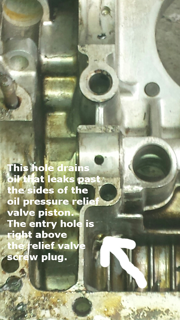
Here’s the early type 4 case

Here’s how the late case is different …
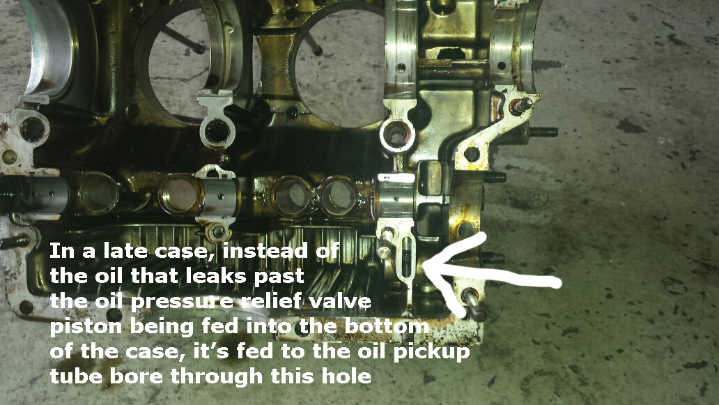
The reason my oil light comes on is because when the vehicle is braking, particularly on a hill, the oil flows to the front of the case. The oil pickup tube picks up oil at the screen and from this hole. If the hole on this side of the case doesn’t mate perfectly with the hole on the other side of the case and since the oil level at the rear of the case is lower when braking, apparently the oil pickup bore picks up air here and not oil as is should. It’s likely that even at higher RPM’s there is the potential for the oil to contain a certain amount of air even though the oil light is out and with a gauge, you probably won’t even be able to tell. A solution to this is to use the early, longer pickup tube. This will block the relief valve inlet hole and you’ll only suck oil. Drill a hole in the galley on the driver’s side of the case to enable draining as in an early case.
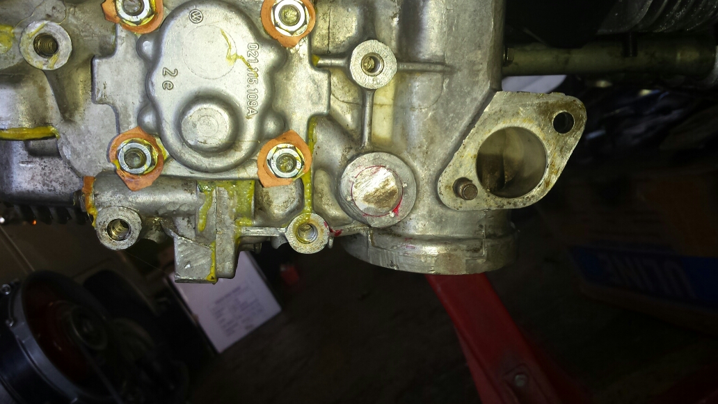
You can fix this problem without disassembly. You’ll need to remove the fan housing and some exhaust and you’ll need to remove the plug for the galley (drill a hole in it and pry), and obtain a 20 millimeter Timesert thread repair kit. Tap the oil galley until the end of the tap contacts the oil pick up tube. Then grind some of the taper off the tap and tap again. You need to have full diameter threads all the way to the pickup tube so the insert will go all the way to the tube and touch it snugly. That’s why you need to grind off the taper – gradually, retapping, then grinding more until no taper left. You’ll also need to grind the top of the insert off so it will go all the way into the case. Be careful. Tap several times so the insert will turn easily. Use grease on the tap to catch cuttings (a little aluminum will not hurt anything so don’t sweat it if you think you got a molecule or two in the engine). Use Locktite on final installation. Make sure the insert makes contact with the end of the pickup tube and mates with it. The insert blocks the inlet and you’ll never suck air again and your oil light anxiety will disappear. The Timesert kit is about $250. You’ll also need to make the plug for the galley on a lathe. There’s not enough material for a threaded plug’s required threads. Make it like a cork and the same diameter as the original. Use Locktite a pound it in like a nail. You Use File it flush with the surface of the case so it won’t touch the rear engine mount bracket.
Here’s the bore plugged after fitting the Timesert …
If you’re putting it together, using the early, longer pickup tube is good insurance. It fits perfectly and blocks the hole. Be careful when fitting so as not damage the o ring on the sharp edges of the hole you’re trying to block. Use WD-40.
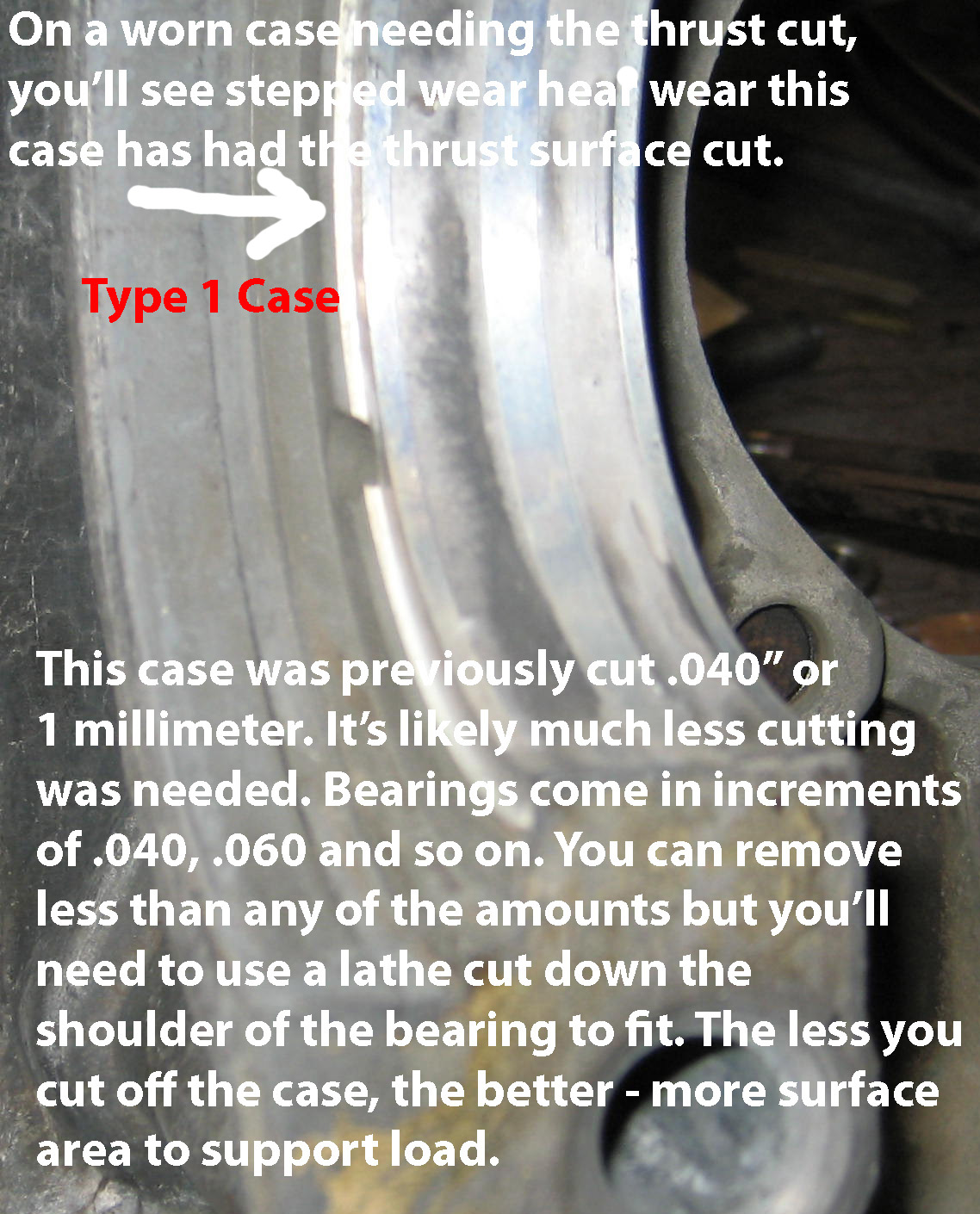
Type 1 engines have soft cases and the spigots for the cylinders often have stepped wear where the cylinder mates with the case. You can elect for machining but I think it’s a waste of money. The cylinder creates the wear because that’s where it wants to be. Of course, with real loose heads it can be real bad but I’ve never seen a case that I didn’t think could be cleaned up well with lapping. This creates positive sealing and thus no leaks …
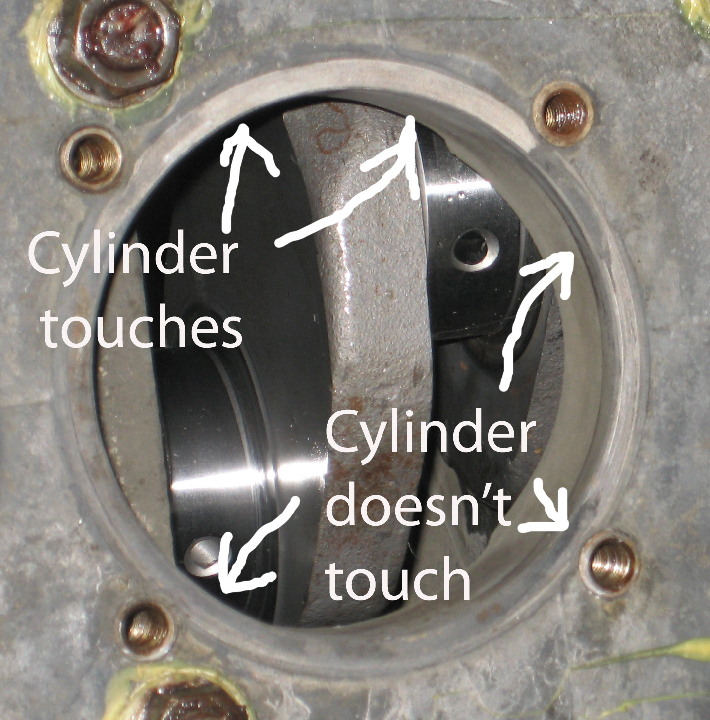
.
Put a rag under the cylinder to keep the lapping compound off the crank (probably won’t matter – lapping compound is pretty tacky). Apply lapping compound to the cylinder, drop it in and make like you’re rubbing two sticks together to start a fire. Do it for a minute, rotate a bit and start again …

When you’re done it should look like this …
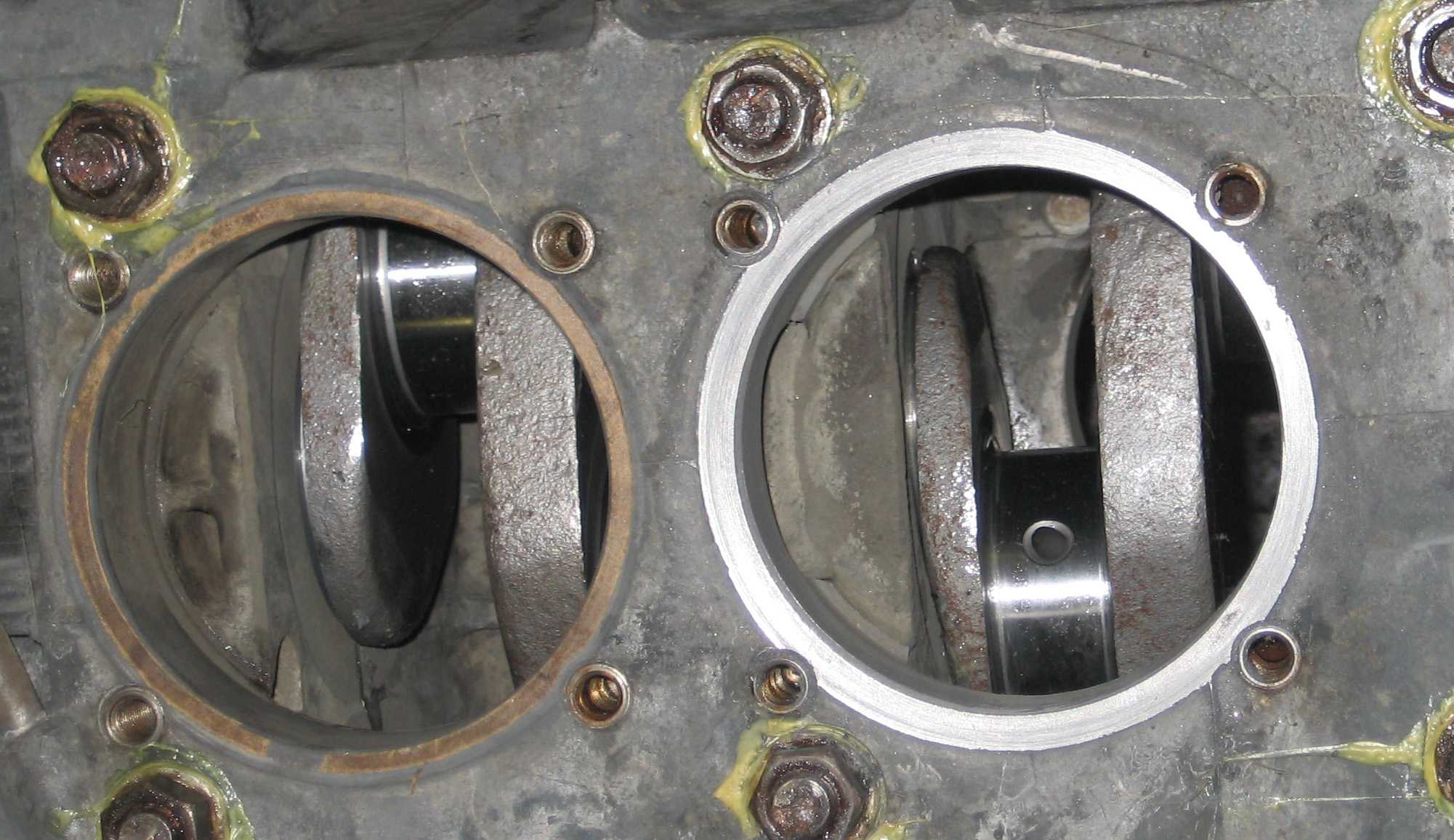
You’ve only taken off what’s needed – maybe a couple thousandths of an inch. If you opt for machining, it’s gonna be about 40 thousandths. Big difference. With lots of glue (how much is too much, really?) between the case and the cylinder and the proper gasket, and the heads nice and tight, it’ll be many tens of thousands of miles before there’s any leakage here. This is a real common area of leakage on Lego Style engines with very low mileage but it won’t happen with non-Lego Toy style assembly techniques.
Here’s some connecting rods …
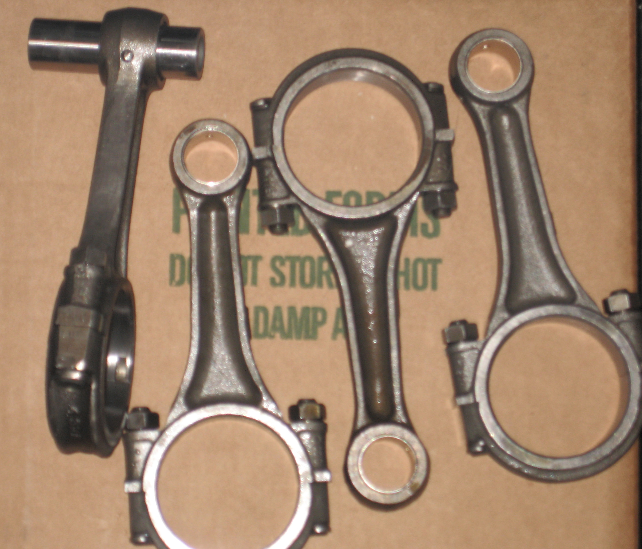
The wrist pin bushings are new. I told the machinist I want zero play between the bushing and the wrist pin. The pin should just barely fit. It’s hard to line up a pin when the busing has zero play but when the pin does go in, it should move smoothly. More on that later. Just tell the machinist you want zero play. Bring one wrist pin from the pistons you intend to use with you to the machine shop since they vary and the machinist will have a reference for measuring clearance, of which there should be none discernible when attempting to wiggle the pin. Replace the wrist pin bushings every single time you rebuild any engine.
Before you install the pistons, for one rod at a time, pick a pin and try to install it into the bushing. If it binds, you need to make it go in easy enough so when it’s on the piston, you can install it. Use WD-40 for lubricant for this trial fit. If it is binding, clean the bushing real good with brake or carb cleaner. This will remove any micro particles of bronze left from the honing process. If this doesn’t do it, use fine wet-or-dry sand paper and WD-40. Clean up the area around the the holes – there may be burrs from the drilling but the binding can occur anywhere. Sand, clean, repeat until the pin is installable. After it is, go on to the next rod and piston.
Here’s the big end of the rod. This rod is quite usable – you can see the cross hatch pattern from previous machining. If it’s smooth here with little to no cross hatch pattern showing, this is because the bearing is wiggling. The crank may be worn but the rods need to be redone on this end – the “big end of the rod”. If the old rod bearings showed a lot of wear – as in a lot of copper showing – have the rods checked even if you see the cross hatch pattern. This is the most critical machining in the engine and the tolerances are microscopic. Sloppy machining may be the cause of your worn bearings in such a case.

If there is little honing left visible and significant amount of a smoothness, have the rods done. A little smooth is ok, particularly at the ends near the studs, it’s ok. This is common; normal. If your rods look nice and the crank measures ok but the rod bearings are showing copper, have the rods checked anyway. The last machining may have not been done right. this is the most critical machining in the entire engine.
I put the rods on after I put the case together. If you have big hands, this may not be possible. Find a cute girl with tiny fingers. Or do it before assembly of the case. Tighten to 35 foot pounds for all models with the engine in the back or use the book torque of 25 pounds. If you tighten to 25 and take it apart in 3000 miles, the rod nuts will seem so loose you’ll wonder why how the rod managed to stay on the crank. Of course, if you need to be protected from yourself, use 25 like the book says. Incidentally, 36 horsepower engines book spec was 36 foot pounds.
So you’ve put the rods on and managed to slide the wrist pins into those nice, snug wrist pin bushings. Now rotate the piston back and forth and make sure the pin moves with the piston. This is your assurance that the pin is not binding in the bushing. If the pin is stationary relative to the piston, polish the bushing a bit with super fine sandpaper and WD-40 until you get the proper result. Realize, it the pin is fixed to the bushing, it can free the bushing from it’s press-fit in the rod. Makes a not so nice noise on a running engine.
The wrist pin clips should be situated like this …
and the rings should be situated like this with the oil ring scraper rails at about 10 o’clock and 2 o’clock and the first and second rings (compression rings) situated at about 10 o’clock and 2 o’clock also. But the thing is – it probably doesn’t make any difference so protractors are not necessary …
Now we install one cylinder with no gasket and secure it with whatever we have laying around …
Make sure it’s snug but don’t tighten too much or you’ll break it. Try to arrange your implements so they engage with the ridge rather than the fins themselves.
Rotate the engine to TDC on any cylinder although in the pic it’s number one. Measure the deck height – the distance between the top of the cylinder and the top of the piston. Measure carefully. You can use a bar across the cylinder and feeler gauges or a depth gauge at 4 places around the circumference and take an average of the 4 measurements.
Now onto the cylinder heads … click here for a primer on cylinder heads.
Ok, now you’ve read all about cylinder heads. Nicely ground valve seats should leave marks like this after after lapping …
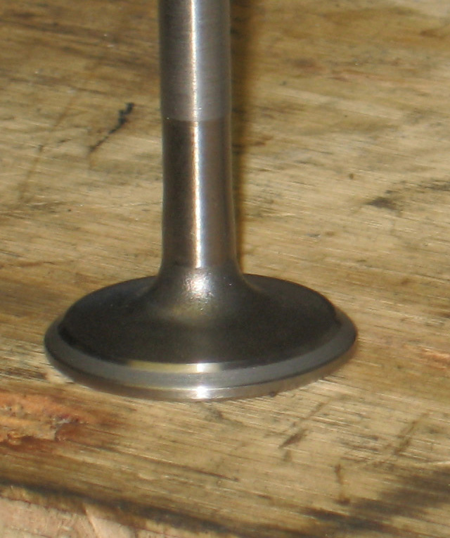
Not like this …

Notice how the mating surface defined by the lapping mark is touching the edge of the available sealing surface – it should be in the middle. It’s best to have the lapped surface in the middle, as instructed in the official VW literature. This is usually pretty easy to accomplish with exhaust seats but is much harder with intakes. If you do try to accomplish this with intake valves, due to the nearly constant diameter due to the steep angle of the lowest part of the seat, you may have to grind so much off this lower part that by the time you get done doing it, you may have lowered the valve over a millimeter of of depth making for problems when adjusting the valves. So your intake mark may be biased to towards the upper edge of the sealing surface like this …
That’s just the way it is but if you start with new heads, it’s much easier and with new type 4 heads it’s usually a piece of cake to get them in the middle. Realize that with the seat cut at the narrowest width of the range – 1.3 millimeters for intakes and 1.7 millimeters for the exhaust – the mating surface begins wears in and get wider with time and eventually wearing out over time rather than starting out wide and basically beginning to wear out from the moment your start your new engine.
Why Valves Burn
After the valves are installed, you really should check for perfect sealing using a fluid such as solvent or gasoline. Just pour it into the combustion chambers as see if it leaks past the valves. If you have a leak, first try slamming the top of the valve with a big hammer just like the rocker arm does. It may to the trick. If that doesn’t do, it, lap the valve a bit. Use WD-40 when reinstalling. Makes it seat well.
When you start a fire, you start with paper. You light the edge of the paper. It lights real well that way. Lighting the middle is harder. You won’t have a flame until your match puts a hole in the paper. So you light the edge.
Since a leaky valve allows actual flame from combustion to leak past the valve and the edge of the valve and the edge of the seat are analogous to the edge of a piece of paper – it’s narrow, same thing – the valve and seat can get red hot and tiny, spherical particles of metal just leave the seat and the valve. The leak gets worse.
Start out with perfect valve sealing and your engine will last forever, assuming you’re understanding and applying the other ten million words on this page. I promise.
Before you install the valves, check the keepers – when placed on the end of the valve and held with your fingers, they should no not wiggle – there should be a gap
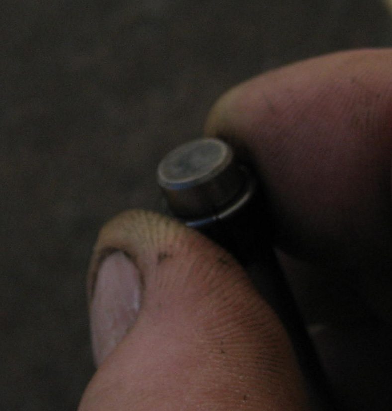
No wiggle implies a micro-gap like this –

Just grind the edges of the keepers a on a bench grinder a little at a time and keep trial checking the fit until there’s no wiggle and you feel a tiny gap and that’s enough.
No wiggle between these two parts and the valve guarantees maximum engagement in the grooves in the valve which greatly reduces the likelihood of this happening should they fall out …
Full engagement and no wiggle makes for a quieter engine too. Most keepers – new or used – wiggle. Always check.
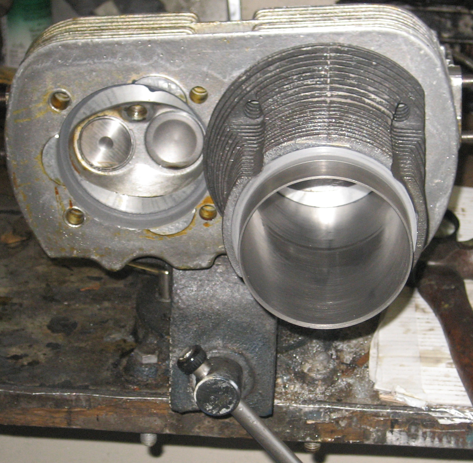
Anyway, now with the heads done and the pistons installed, it’s time to check the compression ratio. First you’ll need to install the cylinder like this …

For flat top you can measure at the middle of the piston but for dished, I measure at 12, 3, 6 and 9 o’clock with a depth gauge then average the results for a final ansah.
I got .6, .6, .57, and .57 in millimeters for 12, 3, 6 and 9, in that order using a depth gauge. Measure a whole bunch of times and not repeated measurements to rule out anomalies in your measuring.
My average is .585 mm.
You’ll need the radius of the cylinder in centimeters to determine volume. 1/2 the diameter in millimeters is 47 millimeters so it’s 4.7 centimeters for the radius.
Realize the engine volume is measure in cubic centimeters, not cubic millimeters to we multiply the above figure by 10 and the result is …
.0585 centimeters for an average. Round it off to .058 centimeters. That’s the deck height.
The best way to measure deck height is at the four place previously mentioned. That way, if you have .2 mm at 9 o’clock and 1.2 mm at 3 o’clock, you can be very certain you have a bent connecting rod. With a rod in this condition, if you place the piston at bottom dead center, you will definitely find the rings will not be parallel to the case surface were the cylinder mates to the case.
Typically, when rods are re-bushed, the machinist should check the rods for straightness. They can usually be straightened. This is common machine shop procedure. A slightly bent rod is not something needs to be replaced. Just ask the machinist for “pin fit and align”. You’ll get new wrist pin bushings and straight rods. Make sure you bring a wrist pin from one of your pistons for the machinist to use as a reference and tell him you want “zero play” between the pin and the bushing.
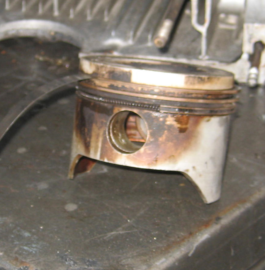
The next step is to measure the dish in the piston in the above photograph.
Just place a plastic plate like this over the dish. Put a smear of grease on the plastic to seal the solvent in. Pour the solvent in with a graduated cylinder like the one in this photo.
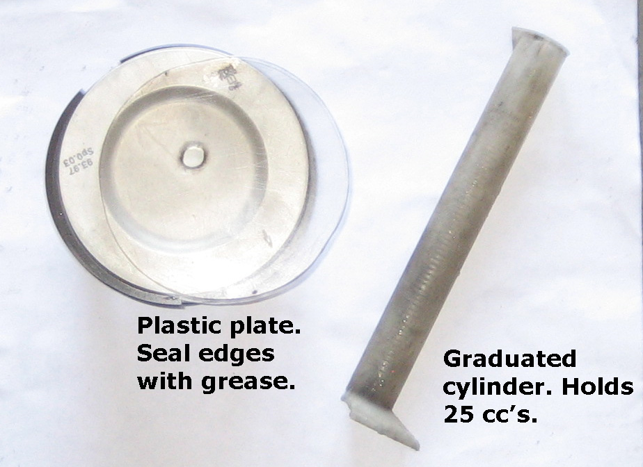
The piston above is from a 2 liter bus engine. Dish volume as measured is 15 cc’s.

My plate won’t cover the entire chamber, it fits just inside the step because it’s too small but it will fit across the step on a type 1 head. I place it on the head with grease and carefully pour fluid in from the graduated cylinder to determine volume of chamber. Use gasoline or solvent. Do it couple times if necessary. Realize, this isn’t heart surgery. Measuring to the nearest zillionth of a cc is unnecessary. But it never hurts to do it a second or even third time to dial in the procedure. Plus or minus a half cc is fine.
I got 49 cc’s volume for a new 2 liter AMC head.
Since my plate won’t reach all the way across, I measure the depth and diameter of the step with a depth gauge to be able to determine the volume occupied by the step. It’s .75 millimeters deep and 94.9 millimeters wide. Notice it’s a little wider than the bore so if you have zero deck height, the piston won’t his the cylinder head.
Converting to centimeters (multiply by 10) I get ..
.075 centimeters deep and 9.49 centimeters wide. That’s the diameter. We need the radius – diameter divided by 2 which comes to:
4.745
The formula for volume of a beer can is the area of the bottom (base) of the can times the height of the can. In math, volume often defined as “the area of the base times the height”.
Same for the step …
The formula is
Pi times the radius squared (area of the base) times the the height (depth of the step)
That’s 3.14 x 4.745 x 4.745 x .075
The answer is 5.305 cc’s.
For deck it’s the same formula with different numbers …
3.14 x 4.7 x 4.7 x .058 (average deck height)
The answer is 4.025 cc’s.
Now we have all the volumes to determine compression ratio:
Head volume – 49 cc’s
Step volume – 5.305
Deck volume – 4.025
Dish volume – 15 cc’s
Cylinder volume (1/4 of the engine displacement) – 492.5 cc’s for a 2 liter bus engine.
Compression ratio is the total volume with the piston at bottom dead center divided by what’s left with the piston at top dead center …
head volume + step volume + deck volume + dish volume + cylinder volume divided by head volume + step volume + deck volume + dish volume
We’ve got all the numbers now so it’s this …
49 + 5.305 + 4.025 + 15 + 492.5/49 + 5.305 + 4.025 +15
simplifying a bit we get …
73.33 + 492.5/73.33 which yields a compression ratio of 7.7162
But since we measured deck height without a gasket and a gasket adds volume to deck height, we add the volume created by the .022 centimeter thick type 4 stock gasket. Since the gasket lifts the cylinder, we use the same radius as the bore as we did for deck height.
Volume is 3.14 x 4.7 4.7 .022 for volume of 1.527 cc’s.
** I always use the old type 4 cylinder base gaskets because they’re already compressed and thus, theoretically, your head will stay tighter for a longer period of time vs a new gasket that hasn’t been compressed and heated during the previous rendition of your engine. Clean up the gasket (minor ridges and old sealant) with solvent or WD-40 and fine (worn 380 or similar) sandpaper before use.
**
Add this gasket volume to the top and bottom of the equation and you get 7.5789 for a compression ratio.
Stock ratio by the book is 7.3. You’ll have to add shims under the cylinder to get it. You determine increased volume of a shim just like with the gasket and add to top and bottom of the equation.
The 1966 bug engine of 1300 cc’s came stock with a compression ratio of 7.7:1. Anything below 7.8:1 is fine with me. And with a higher ratio than 7.3 for a type 4 bus engine, you’ll get more pep and get over a few more hills in 4th gear rather than 3rd. So I’ll leave it at that.
Never assemble the engine if the distance between the top of the piston and the head surface is less than 1.5 millimeters or your piston will begin slamming the carbon on the head over time and eventually the head itself as play develops at the rod bearing and the wrist pin bushing. You may not notice this but this problem translates into hard starting (starter has a hard time turning the engine and long cranking times till finally starting due to extremely high compression ratio this condition can yield and to the resistance created when the piston is contacting the cylinder head). This will eventually destroy the engine. If you deck height is too little, add shims under the cylinder, never at the head. Adding a gasket here will only add one more place to eventually leak. Even copper gaskets will not result in long term sealing. Only with no gasket will you get maximum engine life. With stepped heads, achieving adequate deck clearance is seldom an issue but if you’re using a head with no step, be very certain you have a reasonable amount of deck height. Again, never use the gaskets that come in the type 4 gasket kit. Just throw them away and compensate only with shims under the cylinder. If VW had originally built these engines with no gasket at the head and increased head torque to 40 foot pounds, these engines would’ve lasted a lot longer. Now it’s your turn to fix this inherent design flaw. Realize, all air cooled VW engines never had a head gasket – only type 4’s. Oops!!! Oh well, nobody’s perfect, even the engineers at VW.
Now lap the cylinders into the head and mark them so during assembly they go into the same place on the head you lapped them in. Most heads that get flycut for wear here will be fine with must lapping. And you loose a lot more metal with flycutting whereas lapping removes virtually nothing in comparison. You don’t have to believe me but … yeah, lapping works perfectly. And if you do flycut, lap anyway. Lap until you have uniform color all the way around the combustion chamber and no apparent low spots. Lapping is just as important and those brand new bearings you bought.
Now install the cylinders. Flood the rings with WD-4 then install the ring compressor. Then flood again. The smear a little engine oil on each piston skirt. Now for the sealant. For proper sealing of the base of the cylinder use Gaskacinch first, then the paper gasket, the lot’s of 3M Yellow Weatherstrip adhesive. Use Gaskacinch between the gasket and any shims you may need. But use the 3M stuff as the final sealant that will seal between the cylinder and the case. Use a lots of 3M sealant. Load it up. I may run down the side of the case and the dripping may nearly reach the floor is the engine is on a stand but what would you rather have – long drips yellow glue running off the case or a wet engine in 6000 miles? I’ll take glue now over oil any time. Realize when you use sealant, you’re not painting the engine with a brush of sealant, you want the sealant to actually do something. Think about what’s happening. And 3M sealant will not only seal between the parts, alongside the mating surface, it literally creates a dam the oil must overcome to eventually leak and with sealant between the parts and alongside the mating surface, it’ll be a long time before you’ll see any leakage here.
Now it’s time to install the air deflectors on type 1 engines. For type 4, you do it after you install the head. Trial fit type 1 deflectors until you’re sure they’re nice and tight and won’t fall off. There’s 2 kinds – one kind for 10 mm head studs and another for 8 mm head studs. I can hardly tell the difference. The main thing is they won’t fall off (baling wire wrapped around the cylinders and deflectors is good insurance if you have any doubts about them being secure) but also be sure the corners of the deflectors are bent up a bit and can’t touch the pushrod tubes. They’ll eventually wear holes in them in this condition. About 1/4″ is sufficient. Trial fit tubes to get an idea of clearance. I guess the object is to get the deflector to conform the cylinder as closely as possible. The same for type 4 deflectors. Bend as necessary for both type 1 and type 4.

The next step is putting the heads on. Easy. Spray the head studs with WD-40 and run the head nuts up and down the threads to clean up any old sealant or old Locktite. Clean with brake cleaner.
For type 1 pushrod tubes, never stretch the tubes. Just put them on. Seams go up. Also check for leaks. Even new ones. Put your hand over one end and suck. If a tube won’t hold a vacuum, don’t use it.
Type 4 pushrod tubes go on after the head is torqued. Click here and scroll down for hydraulic lifter preparation for installation.
With the heads in place, put red Loctite under the lower head washers and on all head stud threads. If you don’t put anything under the lower washers, they will leak. Tighten by feel for all the head studs. Particularly for 8 millimeter type 1 head studs. If you tighten by the book (18-20 pounds I think is what the book says), I guarantee you will rather quickly have oil leakage between the cylinder and the case and not much later, combustion by-product leakage between the cylinder and the cylinder head and soon after, you’ll be doing it all over again. 10 millimeter head stud type 1 engines and type 4 engines require 25 foot pounds by the book but 30 to 40 pounds is the way to go if you don’t feel confident about tightening by feel but rest assured, you can do it and you have nothing to worry about, assuming your 10 millimeter head stud based engine has inserts. Inserts aren’t a choice, they’re absolutely required.
It’s time to adjust the valves. Put the pulley or fan on part-way so it’s and line up the mark with the split in the case of at about 11 0’clock for type 4. It doesn’t have to be perfectly aligned for valve adjusting on any car. In this position, the engine is at TDC for either number 1 or number 3 cylinder. With you hands on the pushrods for either cylinder, rock the pulley back and forth a bit. If you find the pushrods moving on number 3, it’s ready or valve adjustment on number one. If the pushrods rock on number 1, it’s in the correct position for valve adjusting for number 3. You should be able to figure out the rest.
Here’s a picture of type 4 rockers installed …
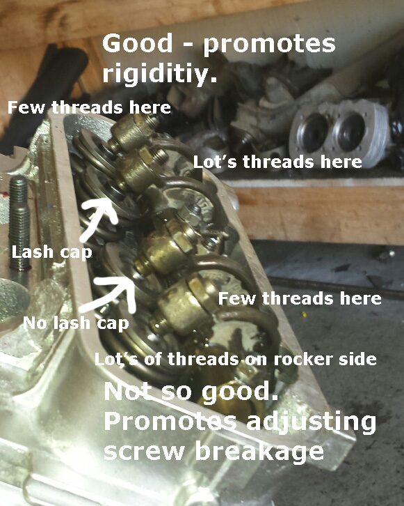
You may have problems adjusting valves. For instance, on type 1, you may find that no matter how far out the screw is, there’s no clearance. You’ll need spacers under the rocker arm. These are available new but are often too thick and thus you’ll end up like the photo above. You may be tempted to compensate with lash caps as above. But you can use a thinner spacer – use 10 millimeter wavy washers. They should all be the same thickness. The thing is, it doesn’t matter what you use, just try to compensate right amount for the best result, not the prettiest spacer. Again, simple washers work well and come in zillions of thicknesses depending on where you get them – they vary from store to store, day to day.
If you do need lash caps – for instance a type 4 engine with a reground cam, German case, Brazilian pistons and cylinders and new AMC heads made in Spain can end up needing them – use none thinner than 2 millimeters in the area that goes between the tip of the valve and the tip of the adjusting screw. Thinner ones (1 millimeter thick) are easily pounded thin and a hole will result where the screw pounds right through the lash cap.
I got these from Gene Berg. They’re nice and thick between the screw and the top of the valve (2 millimeters) but they’re too long. They come real close to the valve spring keepers. Too close. You can have them ground shorter by Berg (I know Rimco will do it too) but you can do it yourself.
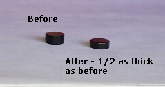
I think these were 6 millimeters long new and 4 now. There’s 2 millimeters left to overlap the tip of the valve. That’s plenty.
They’re super hard. You’ll need a bench grinder to shorten them yourself. And technique. They need to rotate as you grind and for that to happen you have to hold them lightly just like this and let them spin. They will spin by holding them lightly on the side of the wheel just like this. Be careful – they like to fly and disappear so it’s best to order a couple extras just in case. Practice …
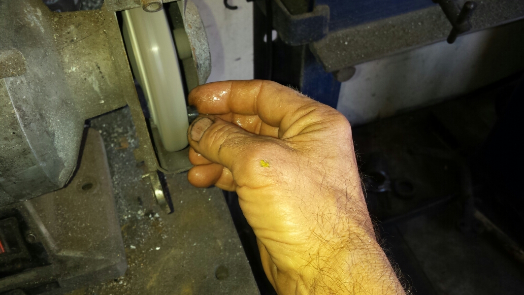
You won’t be able to do it with gloves on.
Lash caps do the opposite of washers under the washers. Lash caps were supplied by VW long ago to cure concavity at the top of the valve on high mileage engines with genuine VW valves. You can use them too – if you can get them to fit – to insure against this problem in the future.
Now that you’ve done all the above, you put everything else on. At least, that’s what I do. Then I set the end play. That way, the engine is real heavy and it makes it much easier to tighten the 36 millimeter nut for the flywheel on the type 1 and also, most stands won’t let you put the flywheel on because the stand is in the way. So I finish the entire engine then put it on a table (floor will work) and set the end play and finally tighten the flywheel but here’s the end play now for continuity in assembly of the engine itself. This is also the time to install threaded plugs in both of these oil galleys on every type 4 engine whether you think they leak or not. They seldom leak on type 1 but they can so if you feel like it, do it.
Click here for the next step – setting the end play …
