I started this a few years ago. Took a real long time. You won’t find this anywhere else. I have no shame. Donations accepted via on home page. There’s typos. Writers – me for instance – make terrible editors. That’s what editors are for. I have no edddisotjsoator . You’re probably expecting this information to tell you the “just go like this”, lego toy style of fixing something. Nah, it’s a bit more involved than that so if you have problems, you can use the only tool no tool manufacturer makes – your head. So read on if you dare.
This is not complicated.
Timing is all about distance. It defines the distance the piston is from top dead center – and thus the distance between the piston and the surface of the combustion chamber. But that would be hard to measure – take engine apart to check distance – so we use degrees and the proper amount of degrees are determined by the car manufacturer. But all cars have pretty much the same timing. Curves vary, methods of adjustment vary, but they all run at about 10 degrees at idle (!!keep reading). Setting the timing at 2500 or 3500 to set it at the max advance is not a good idea unless you want to check the function of the distributor. It’s seldom necessary with VW/Bosch distributors. A sticky advance mechanism is about the only problem you’ll ever encounter with these. Lubrication fixes it and you don’t even have to take it apart. Just dowse it with oil and let it drain. Put a little oil on the felt wick in the middle of the shaft right under the rotor.
First of all – timing. Engine is just like a bicycle. It has a crank and your legs/feet are the pistons. Viewing a bicycle with a rider on it from the right side, the foot pushes the pedal down after 12 o’clock. This is retarded timing – initiation of push is after 12 o’clock. The power in the push happens instants after initiation. Pushing at or before 12 o’clock won’t work.
In an engine, the combustion is the foot. But you must light the fuel and it must begin burning to it’s max so the timing is set advanced – before 12 o’clock. As the piston passes 12 o’clock, the explosion is really happening and the piston is pushed down with the force of the still incomplete burning of the fuel. Finally the fuel is spent as the piston pushes it’s way to 6 o’clock.
The above is pretty much typical on on vehicles with minor variations on where the manufacturer specifies the actual timing but for most vehicles it’s about 10 degrees advanced – before 12 o’clock.
On vehicles with the timing set at idle with the timing set at 5 degrees retarded (after 12 ‘clock), the above still is true because as soon as you increase the rpm’s just slightly, the suction on the retard hose drops massively and the timing jumps to about 10 degrees advanced. The reason for the retarded timing at idle is because it reduces the hydrocarbons to enable to vehicle to pass US smog laws for idle emissions. You can actually static time a distributor with an advance/retard vacuum unit at ten degrees. If did that and started the engine and checked with a timing light and the retard function is working, you timing would now be 5 degrees retarded.
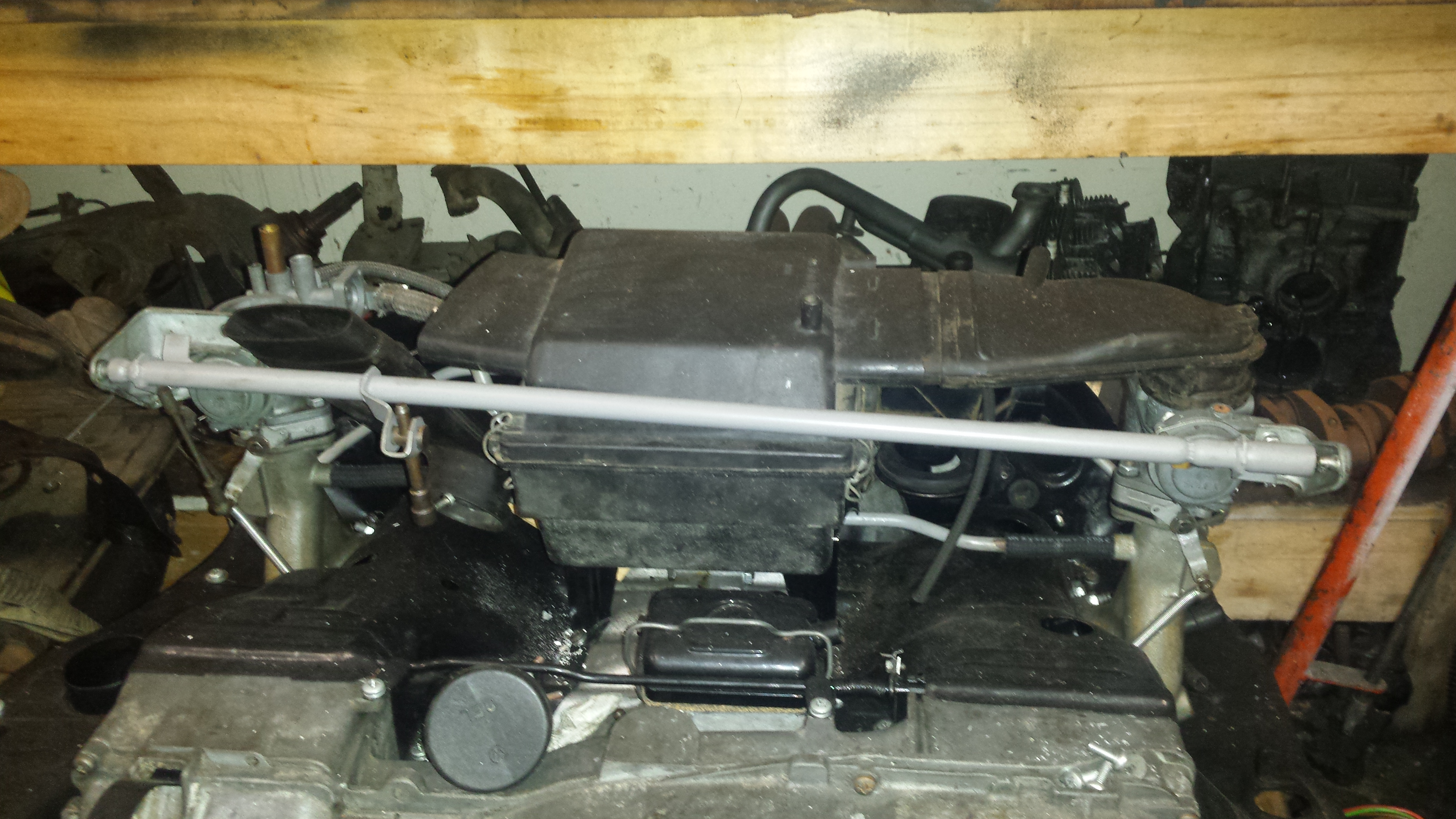
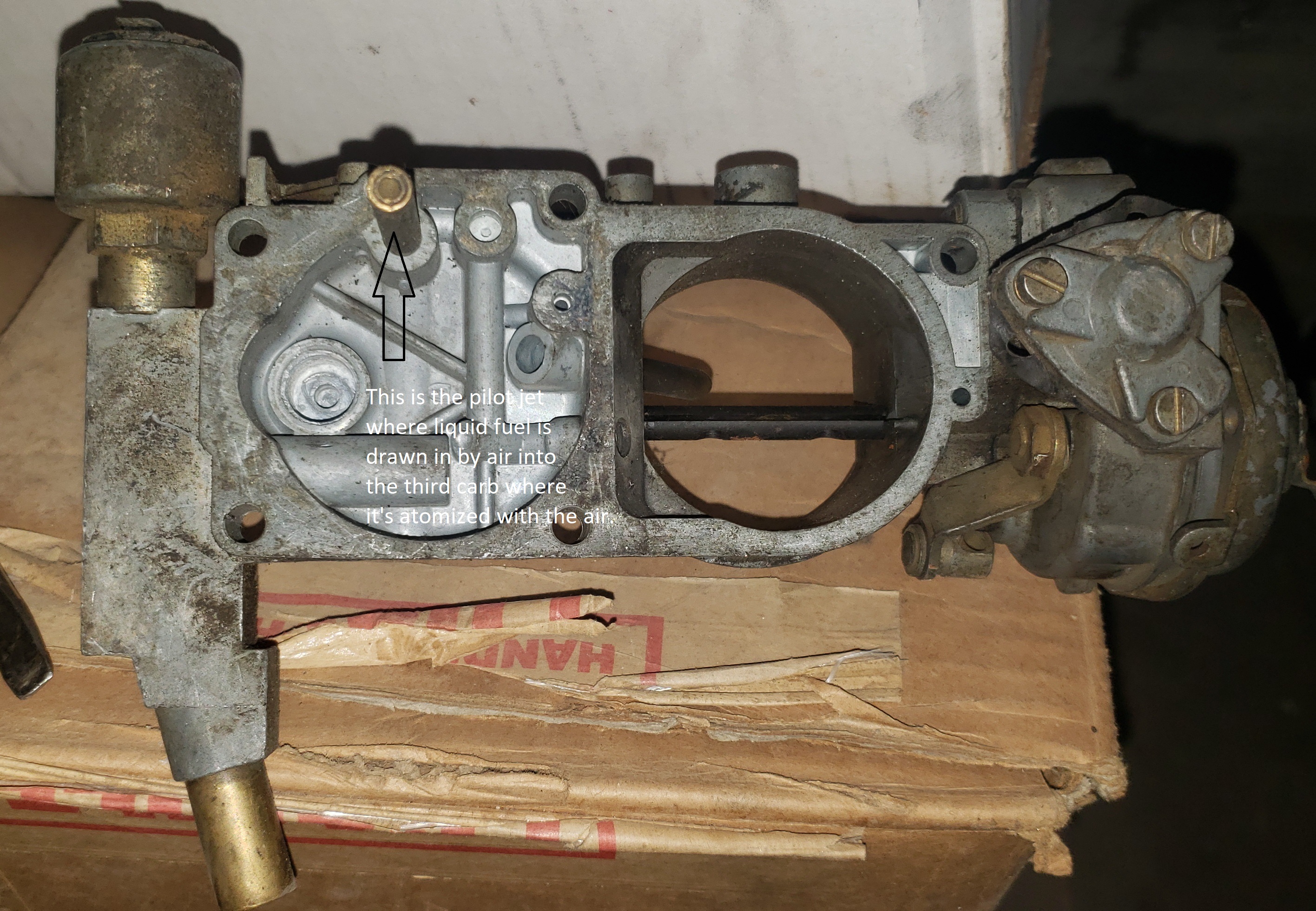
A lot of what follows is what you need to do to make this go away and be able to set your type 4 bus carbs at 10 degrees advanced and completely delete this part of your system. From hereon in I’m calling it the THIRD (carburetor) because it really is a third carburetor but all it does is supply an atomized mixture of fuel to keep the vehicle idling because and allow for smooth take offs and eliminate dying at stop signs when you’ve come down a hill in gear without your foot on the gas because there’s just not enough fuel for this to happen with just the pilot jets on the sides of the carbs because the pilot jet air bleeds are too small – about 1.5 mm for type 4 carbs vs 2 mm for type 3 – among other things. read on.
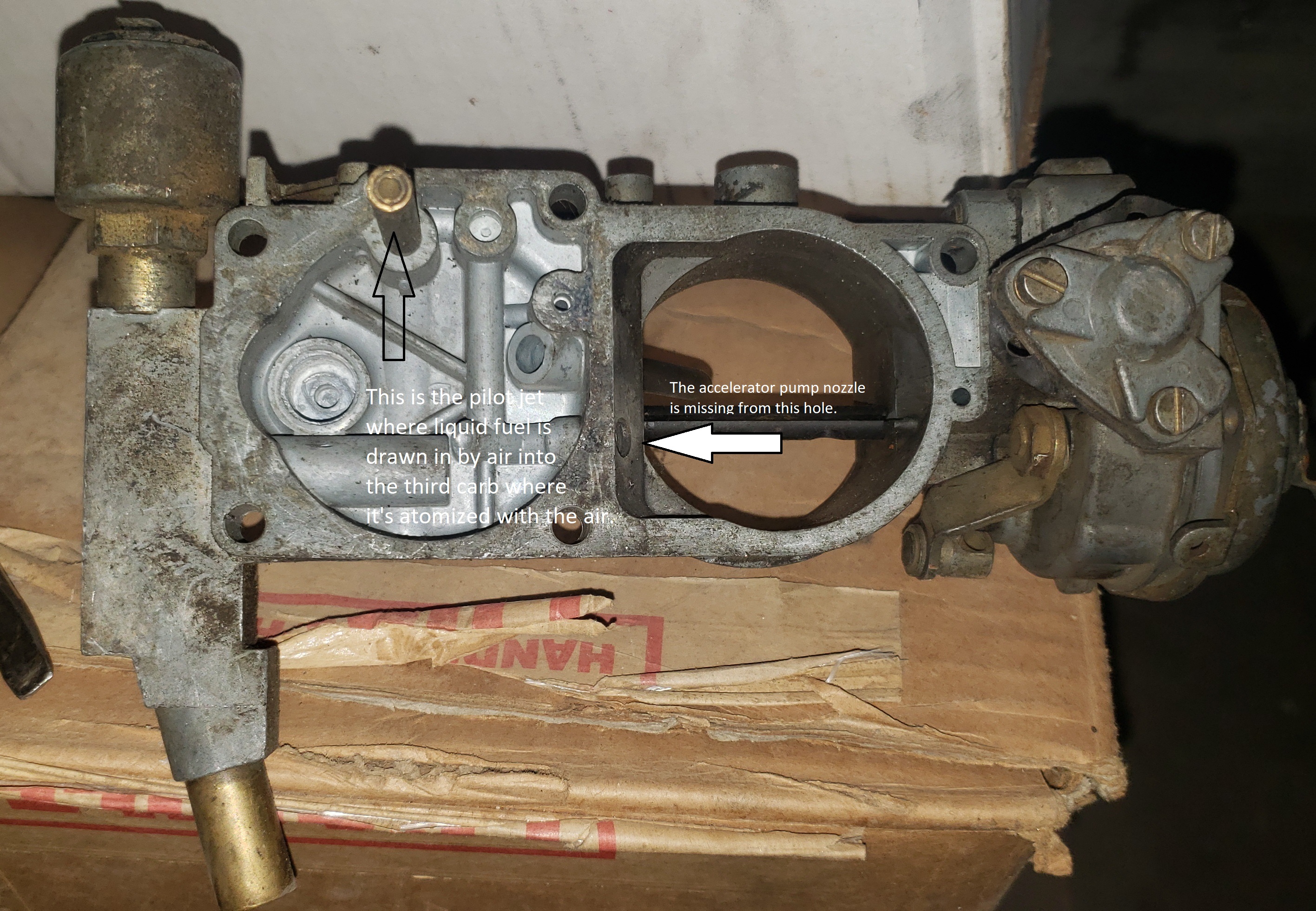
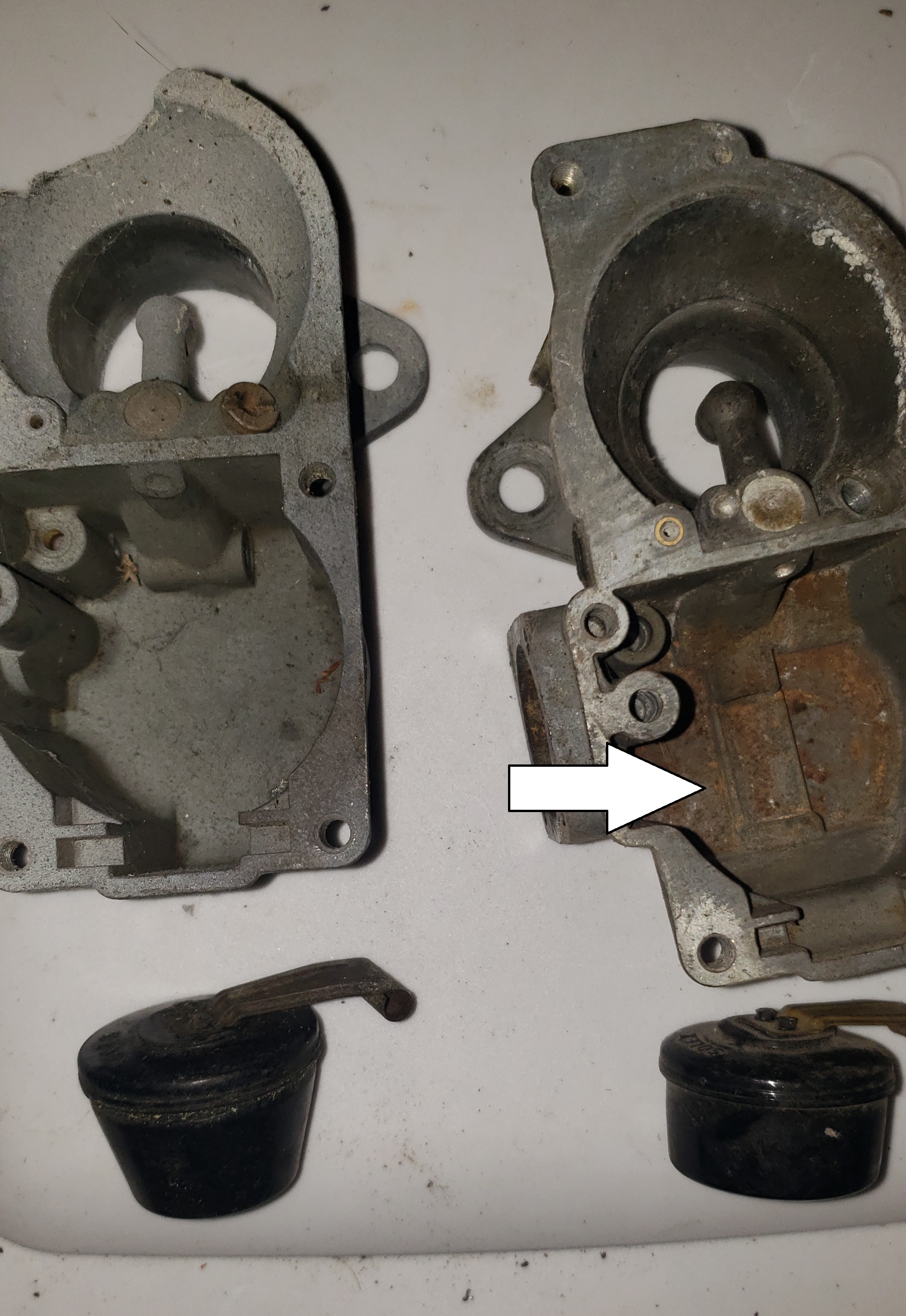
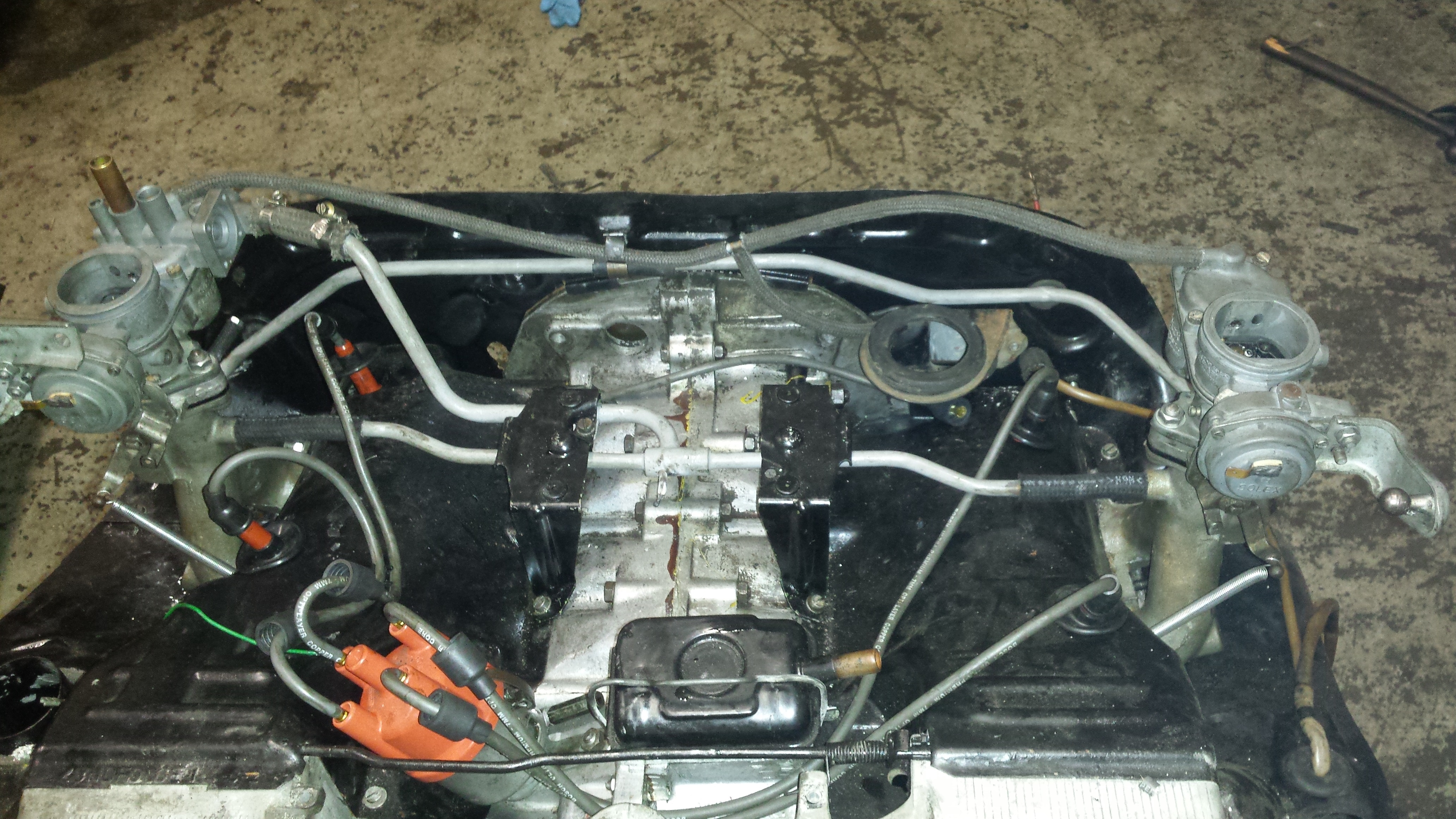
Notice the accelerator pump nozzle is missing on the lower carb. It probably fell out because the stop that’s cast into the carb top that’s there to prevent the choke flap from going beyond vertical broke off so the nozzle became the stop and over time with vibration the nozzle fell out. They’re not available anymore. Peen them well around the collar so they’ll never come out but make sure the nozzle doesn’t rotate by hand relative to the collar -careful, tiny peening may be necessary. You can
also remove the choke shaft and plug with allen set screws. You’ll get better air flow without the shaft. Leave the choke element in place. Use dummy wires and it’ll look totally original. At least remove the flap to prevent nozzle breakage and peen the nozzles. You can load up the cavity under the choke element with silicone to keep the Rolex parts from wiggling around.
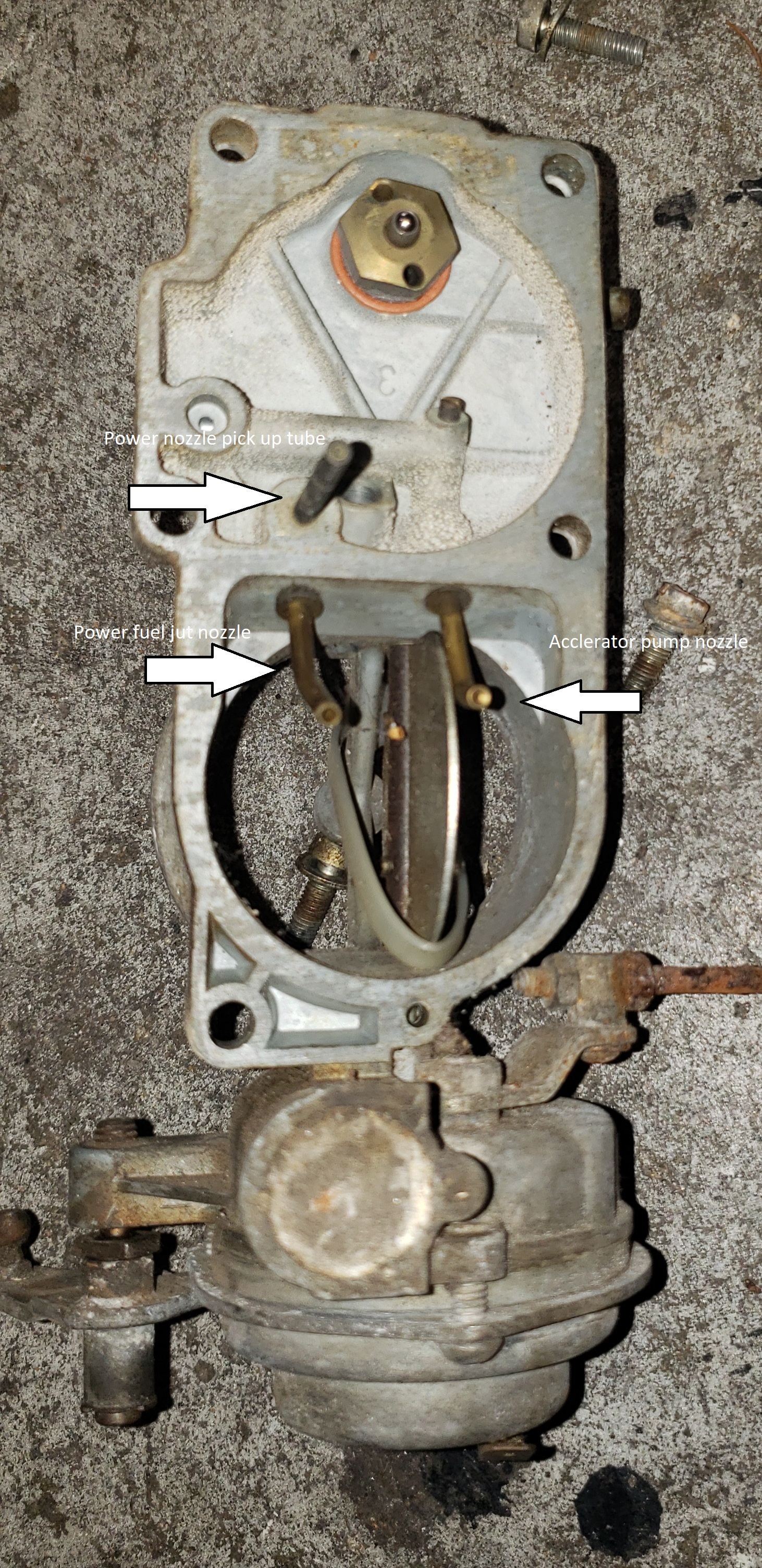
Notice the hole at the tip of the power nozzle is bigger than the one for the accelerator pump. It dumps a lotta fuel you probably won’t need unless you have the original squareback engine it came attached to as new …
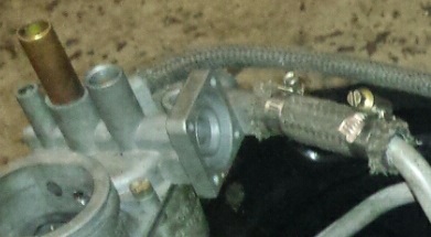
When you’re all done with this, you leave the giant electromagnetic air cut off jet in and disconnected. You can also use a proper bolt instead. Screw both the mixture screw all the way in and also the air control screw all the way in and then plug this pipe right where it meets the carb. Leave the rest of its pipes connected. They act as a balance tube.
Setting the timing at 10 degrees with an 009 distributor for instance will result in a condition where it’s impossible to set the idle at a normal speed because there’s just not enough range of thread and you still have a bunch of air coming in through the hole in the throttle plate in the throttle body on all type 4 bus carbs. And air is what controls speed on any engine – more air equals higher rpms.
This is an old type 3 carb top …
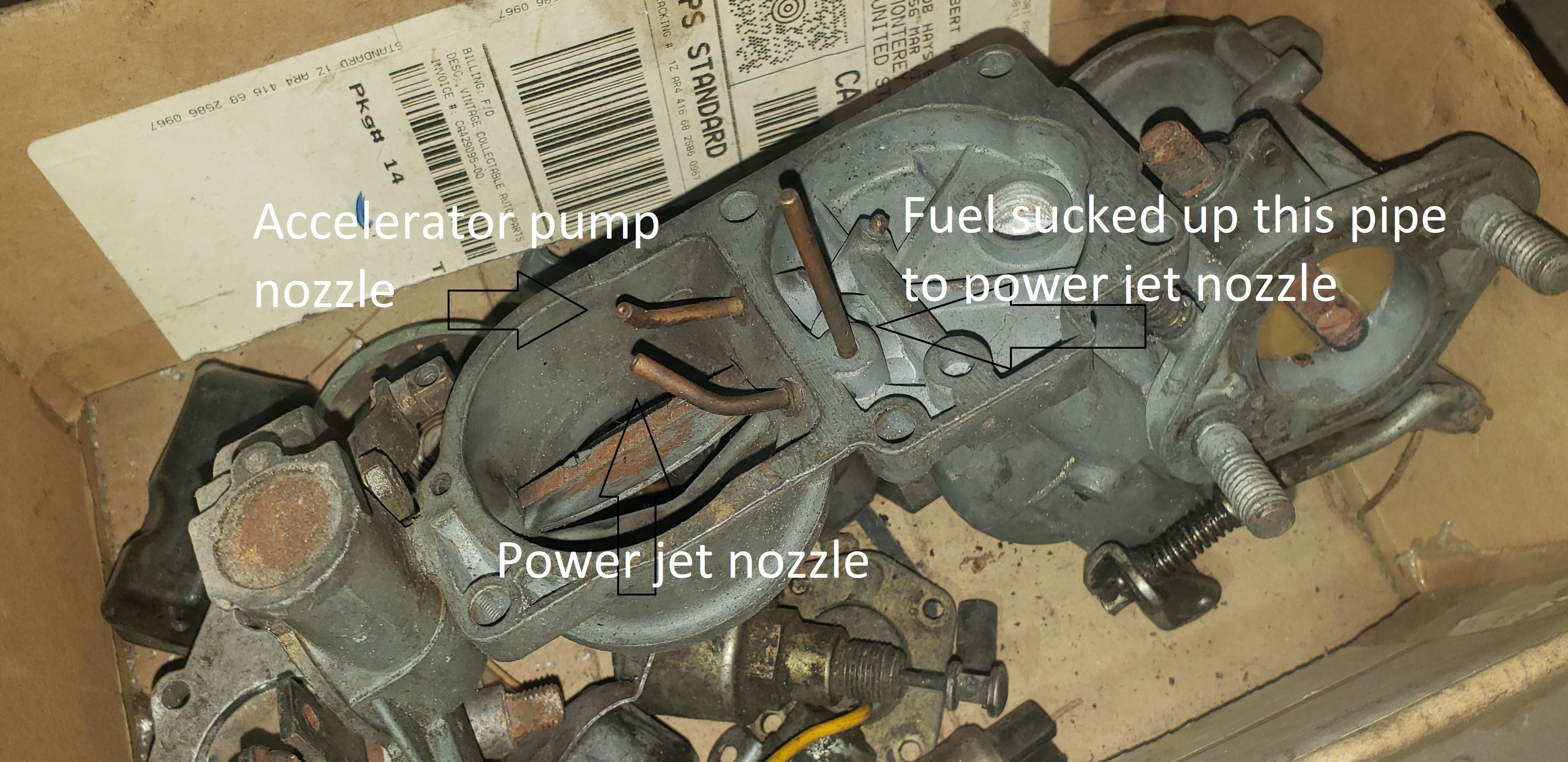
The power fuel jet nozzle can be installed on any PDSIT carb that doesn’t have it by drilling a hole for it and hole for the pick up tube is already there – you’ll just need to find a pair of carbs that actually has it – real old. But you probably won’t need it
The type 3 carb is pretty much exactly the same thing as a type 4 bus carb. There’s a hole for the vertical
pipe in the pic and the channel that feeds the power fuel just is there on all type 4 carbs. There’s no hole for the power fuel nozzle but there’s a boss. You can actually drill the hole and put the power fuel jet nozzle in a type 4 carb. I’ve done it and it fixed it. This is seldom necessary but in this case it was for a 1.8 type 4 bus with AMC 1.8 heads
(AMC 1.8 heads for a 1974 bus – a 1.8 as new – have smaller valve sizes than a real carbureted 1974 bus 1.8 head. The AMC valve sizes are for the one other year of 1.8 type 4 bus and it was fuel injected, thus smaller valve sizes. For any type 4 engine consider using new 1.7 AMC heads and have them machined for a the bigger cylinders if you’re using 1.8 or 2.0 cylinders. Valve sizes on a 1.7 AMC head are 39.2 intake and 32.5 exhaust. For all the other type 4 heads the AMC exhaust is a little smaller up to 1.5 mm. But the intakes are as big as it gets for all type 4 and bigger than any other AMC head Do the seats by the Bentley book exactly lap and check with liquid for leakage and correct as necessary if there’s leakage and tighten the case bolts to 35 lbs and tighten the head nuts to 35 lbs and use good parts and make sure you have zero air leaks and proper carburetion and that trip you’ve been planning to Saturn will yield no getting stranded. Promise. But bring spare fuel pump and stflydat.)
Everybody knows old carbureted squarebacks ran great. Type 4 buses ran great but VW complicated things when they added a third carburetor. But today, many of these vehicles just won’t run right with the carbs they came with. Different shaped combustion chambers, different valve sizes, differences in camshaft profiles – all these things variations are the reason the carbs often just don’t work. Barring air leaks among other things.
But there’s a way around it. For a type 4 it’s a matter of turning the bus carb into a squareback carb. For a type 3 that won’t run, it’s usually adding or taking away the power jet – they usually won’t need it. Changing the venturi sizes – there’s a bunch. 21.5, 22, 24, 24, and 26 millimeter. If your carbs don’t have what you need you’re gonna need other carbs. Quickest solution is to by the Brazilian ones from CB. They have fake type 3 carbs but the throttle body and the venturis fit on a German carb and work. Since the venturi is small (21.5 mm), you can make it bigger on a lathe. The center section (part with the float bowl) of these carbs is useless. I think the emulsion tube (not removable) is different than German carb. There’s no other explanation. A stock single port 67 bus with stock transmission with this center will go 50 mph in third gear with the German center. It’s just hit about 40 mph with the Brazilian center.
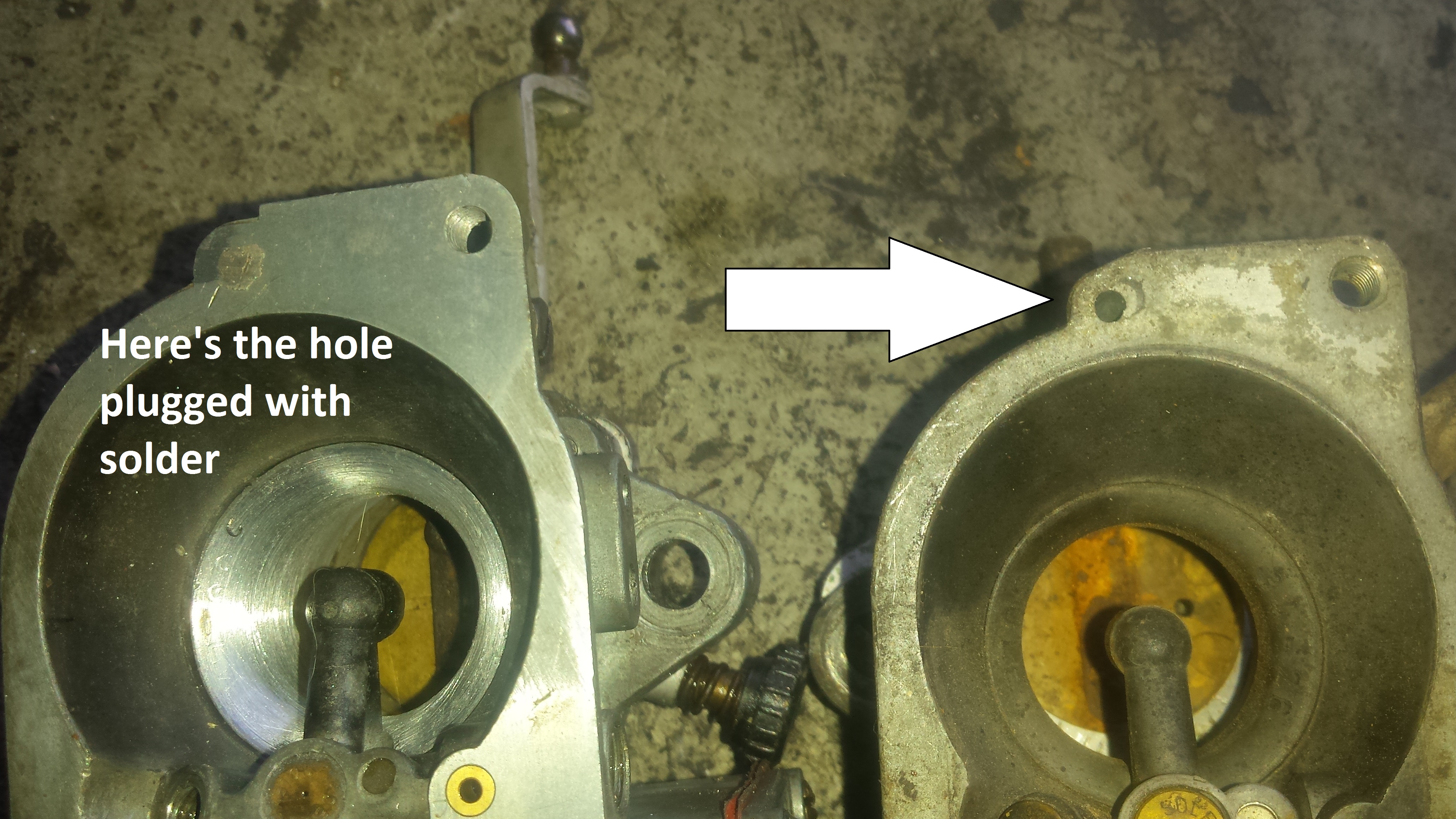
First thing to do is delete the choke. At least pull the flap to save the accelerator pump nozzles. Then plug this hole (air leak) with solder. Just keep pushing it in. Don’t attempt to heat it.
For a type 4 bus carb, solder the hole shut in the throttle flap. I use a mini torch. A soldering gun won’t work …

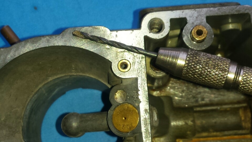
Next, make this hole 2 millimeters if you’re using type 4 bus center sections …
Make sure the accelerator pump works like this. If it doesn’t, figure out why. Sometime the ball seats are imperfect. Take a narrow splinter of wood and that will slide with no interference into the ball hole and push the tip against the seat and twist. This can often fix up a leaky seat. You don’t necessarily need this much fuel but you need a good squirt at the nozzle that lasts up to … “one thousand one, one thousand two … “. Right after you say “one thousand one”, that’s usually enough fuel. Forget measuring fuel volume as stated in the book. This works. If you make the accelerator pump rod longer by about 4 millimeters, you can use the cotter pin or plastic nut adjustment to set the pump volume to zero then see if it runs right. If you have a flat spot, increase volume by moving the cotter pin/plastic nut. Use washers to adjust if needed. The less fuel the nozzle squirts, the better gas mileage you get but you gotta have enough fuel for it to run right – no flat spot. If you can’t adjust the rod to less than “one thousand 3 or 4” for instance, you should probably make the rod longer.
I made this rod a little long so it’s got a little more than just a couple washers. The washers are for adjustment to the minimum gas the bus needs for zero flat spot …

Notice I used studs where the linkage attaches to the carb. These holes like to strip with repeated removal of the bolts. Studs prevent this. Notice the adjustment washers on the accelerator pump link. I used a lotta washers because I made it a wee bit too much longer. But longer is better than too short.
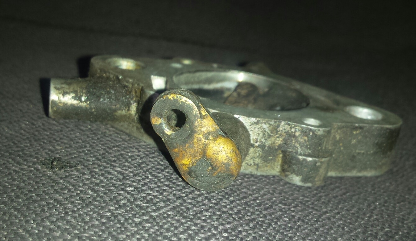
Notice the ball socket at the top of the link rod. The ball has been flipped. As stock, it’s aimed to the left. I moved it to the right so the rod won’t rub on the choke element which is very common. The ball is like a rivet. Grind off the back side, knock out the ball, stick it in the hole from the right side and braze it on the backside. This is my 74 bus. It purrzzzz. It took it to Saturn … twice. Made it back too. No unplanned stops evah. It’s the little things …
This is how you fix elongated holes – braze tiny washers and file as necessary.
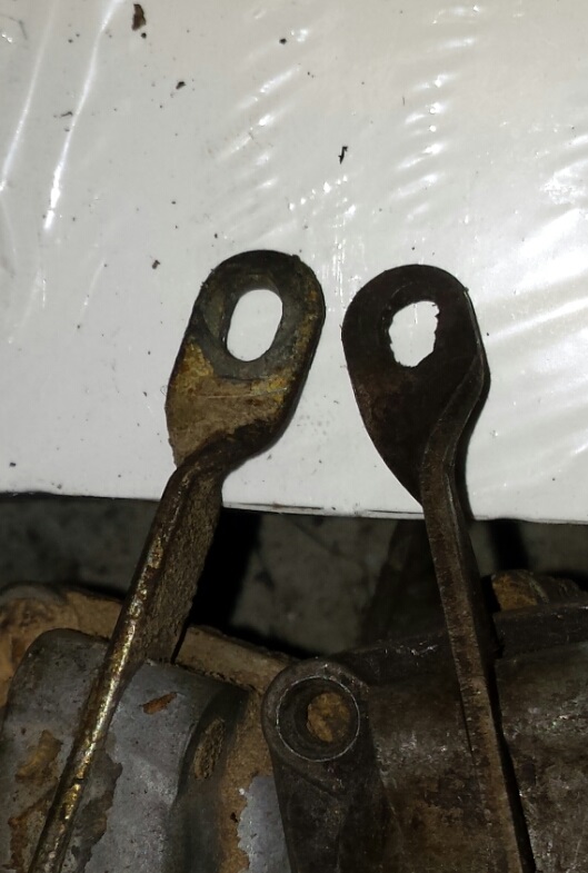
You can fix up throttle bodes and accelerator pump levers but and even the link rod but if it’s really toast make your own and use a die for 5 mm (maybe 4 mm) and use nuts to secure.
Make sure the accelerator pump works like this
Realize just putting the contents into a carb doesn’t guarantee the accelerator pump is gonna work. You gotta check it. You can by a new Brazilian Solex diaphragm for a bug and use it in a type 3 provided you’ve made the rods longer (the pin in the center of the diaphragm is a different length than a PDSIT diaphragm but the Solex part is superior to the low end material in a typical aftermarket kit diaphragm. Making the rod longer compensates for this.
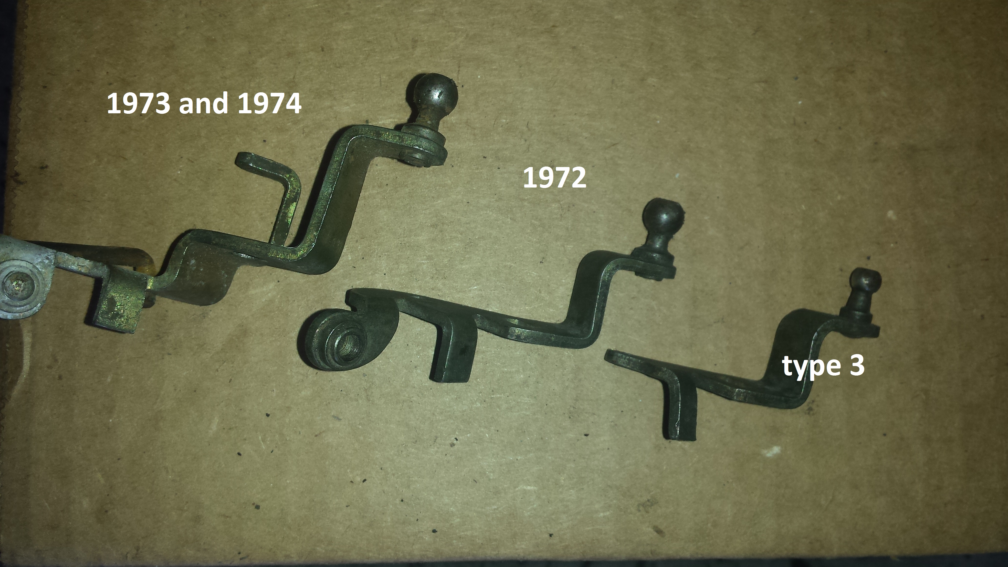
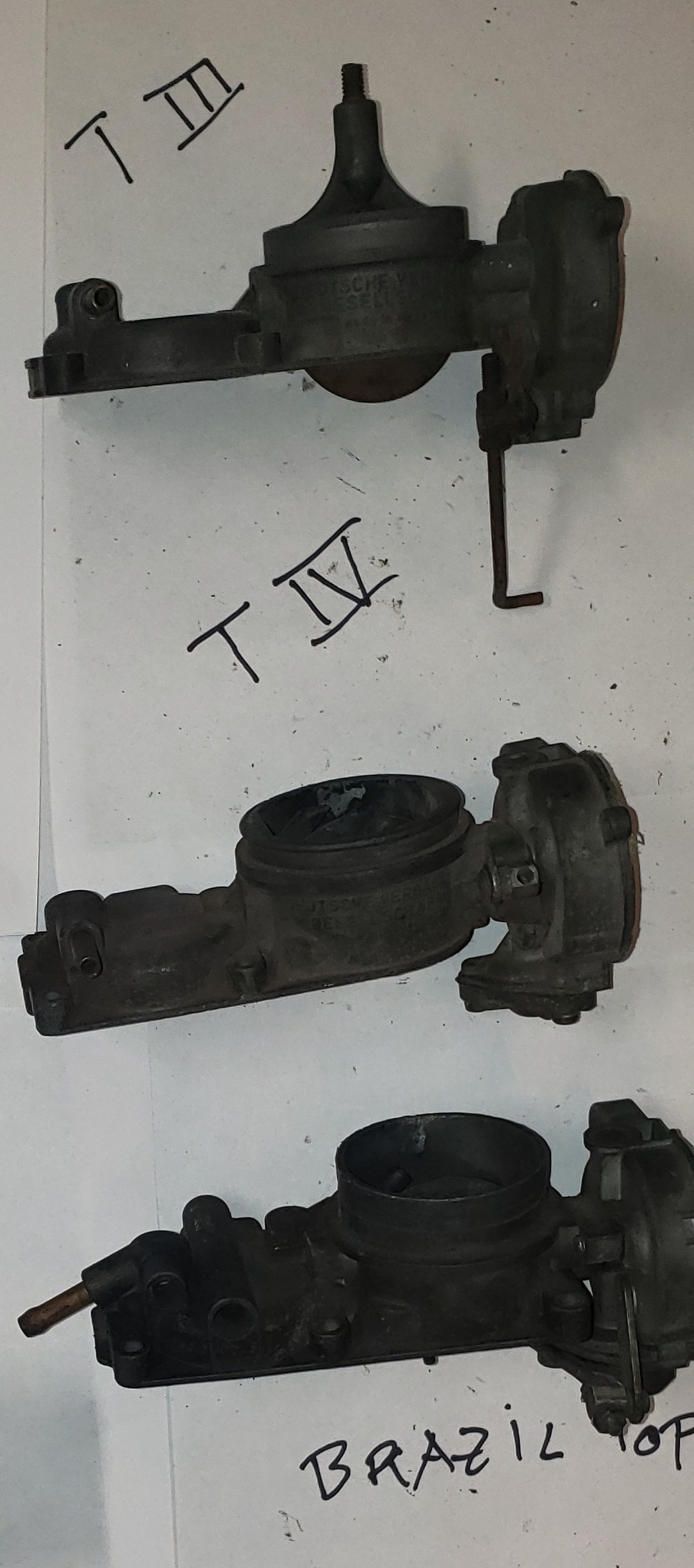
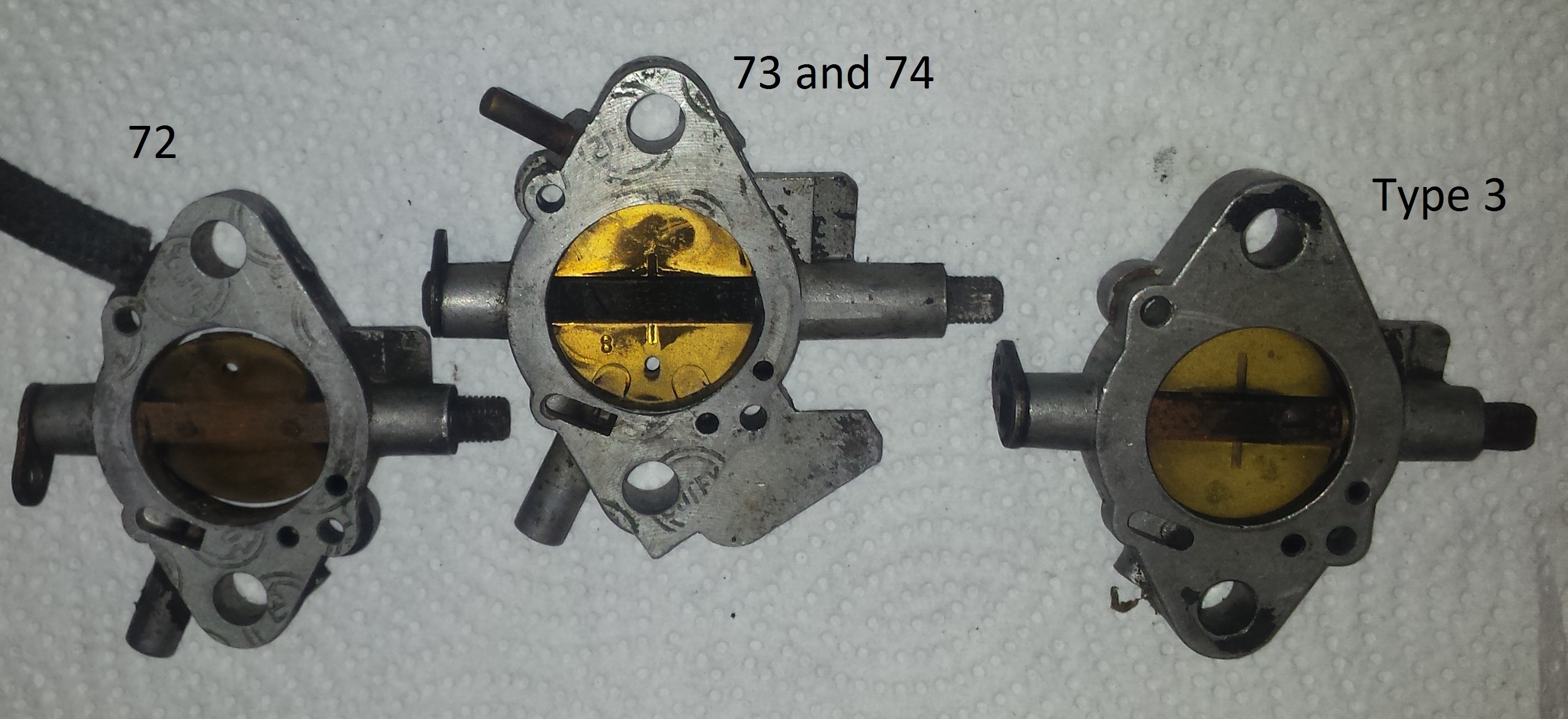
There’ 3 kinds of throttle bodies. 73 and 74 on right, 72 in middle, type 3 on right. Type 3 and 72 bus have same offset thus interchangeable.
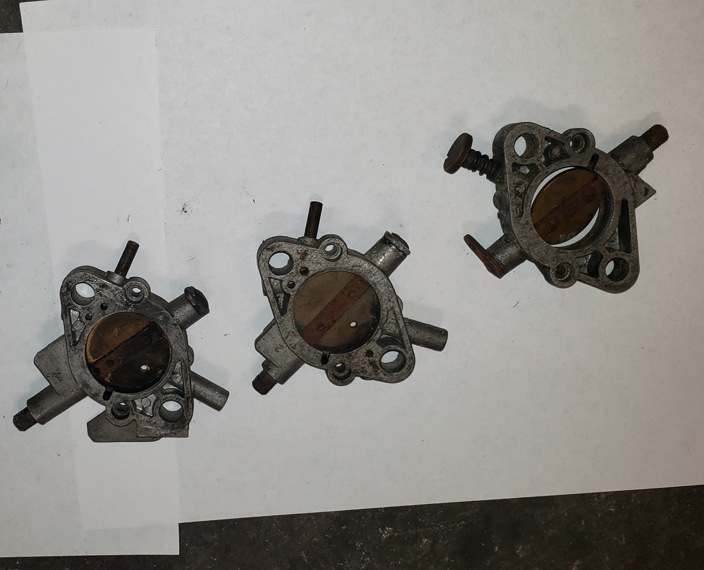
There’s 3 types of throttle body levers The late (plastic air cleaner) ones are longer to clear the plastic air clearer. The short ones work a for squarebacks and 1972 only buses with the metal air cleaner.
This bus has the plastic air cleaner that requires the longer levers but I used type 3 throttle bodies so I had to make them even longer. Took a minute
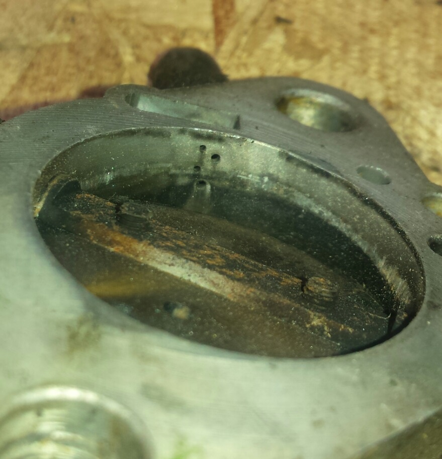
Make sure the pilot jet hole is in perfect condition. If it needs an insert, toss it. Likely the pilot jet will never seat perfectly at the bottom of the hole. The tip must center to seal the tip to the concavity. If not, fuel will leak past the tip into the engine when running. The only fuel you want is the fuel that goes through the hole in the tip of the jet. Repair inserts rarely allow for perfect seating (slightly off center). This sealing is exactly like you find on the fittings for a gas cooking stove. In this pic you can actually see where the tip of the nozzle mated. Def off center.

This never idled right with an insert …

Since the pilot jet when correctly installed results in the tip of it mating with the bottom of the hole rather than the hex head mating with the top of the hole like a typical bolt, you gotta make sure the tip really mates. It may be necessary to taper the hex head. This prevents interference at the hex head enabling sealing at the tip. However, these jets come in varying lengths. Just deal with it as necessary.

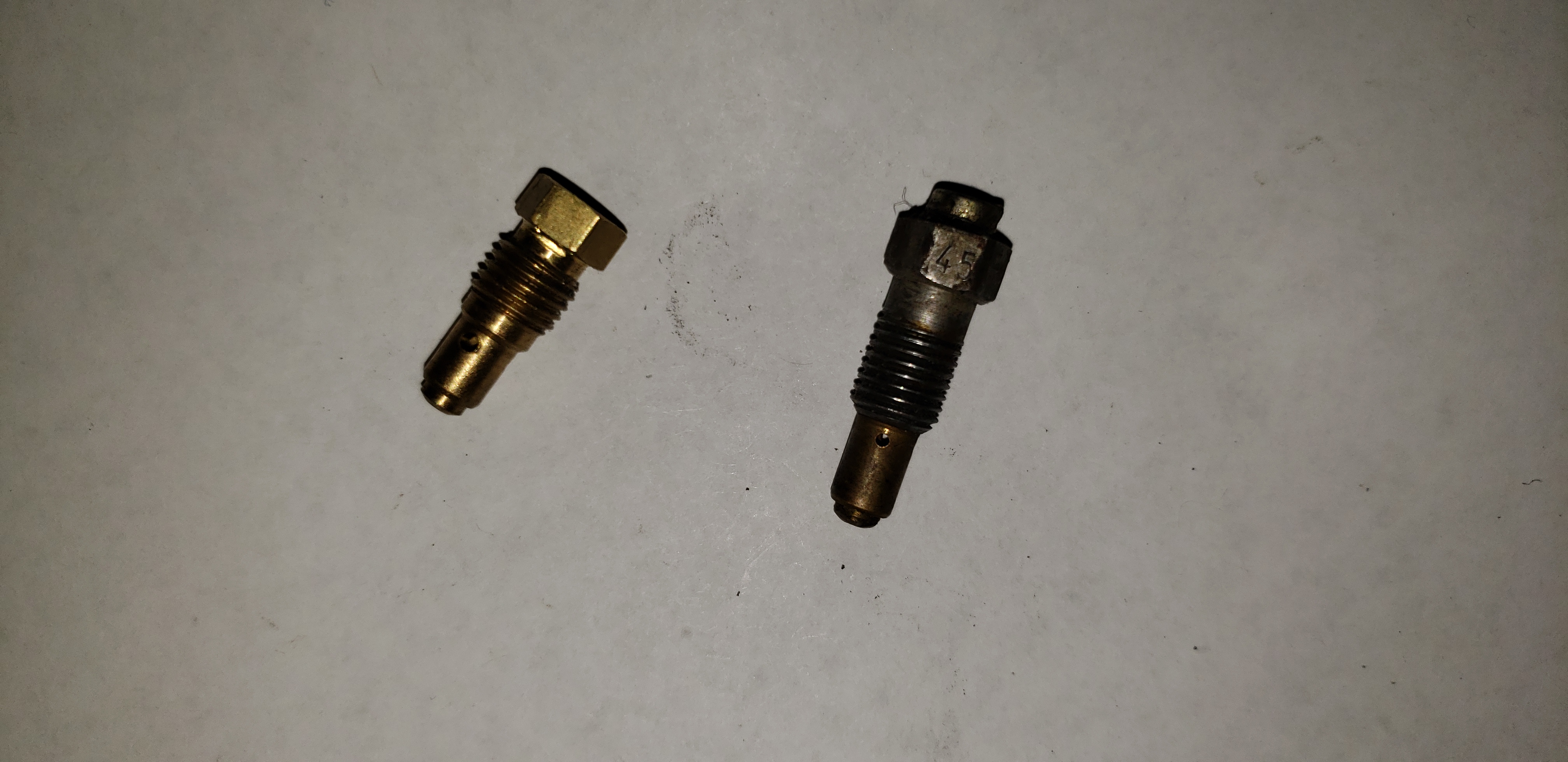
The lower jet is normal and the other is from an early electromagnetic cut off jet which can be disassembled and in this case yielding the smallest size pilot jet – a 45. The hole in the end of the jet for the pin from the electromagnetic part had been plugged with a small screw so it’s useable and can be drilled as big as necessary. New jets are available. Buy several 45’s and you can make them as big as you need. Basically, see if it idles with a 45, if not, make it a 50, if not, make it a 55 … until you’re satisfied with the idle.
Realize VW designed the hole for the pilot jet for bugs probably before WW 2. The hole was never redesigned for the later vehicles with the much much much heavier electromagnetic jet so the electromagnetic jets are often loose and thus hang on the hole and ruin it. So get rid of them and use plain jet, no electrics. It’ll be fine, promise. If your vehicle does run on after you turn it off it’s probably a motor with too high a compression ratio or something hopefully less serious but it’s not gonna be the carbs.
Running on after the key is off is not the timing per se. There’s no spark with the key off. But overly advanced timing makes the combustion chamber too hot and this can running on with the key off.
And too high of a compression ratio does the same thing.
There’s 2 kinds of floats – type 4 and type 3. Type 4 fits type 3 but not the other way around. Make sure the float travels up and down freely with out touching the side of the reservoir particularly the wall between the throat and the reservoir. Arrow points at access channel for main jet that makes type 4 reservoir shallower thus requiring a different, stubbier float. Type 3 res and float on left, type 4 res and float on right.
Case history – 2 liter bus with small valve 2 liter new AMC heads. Stock reground cam, hydraulic
140 airs
130 mains.
Pilots about 55, been awhile. 2 mm pilot jet air bleeds – do this every time.
23 mm venturis. Initially I made the 26 vents a little bigger – would run right at all. 24’s were too big too.
1974 bus, 1.8, new 1.8 AMC heads – tiny valves, NOS cam, solid lifters.
26 mm vents, wouldn’t run.
Ended up with 23 mm vents, big mains, 140 airs, wouldn’t run. Ready to give up. Finally added the power fuel jets – runs like it’s got fuel injection, ie perfect. Mains ended up being 130’s, maybe 127’s.
Dual port type 3
Customer provided NOS 1500 S carbs. I checked jetting and vents. Exactly by the book. Also came with power fuel jets and about 240 or even 280 airs.
Carbs were on the car. Accelerator pumps did nothing. Found that the springs under the diaphragms were too long thus making it impossible for diaphragm to compress and push the fuel.
Upon holding RPMs at about 2000, found lot’s of back smoke coming from tailpipe. Plugged power fuel jets. No more smoke.
Drove it – soggy. Put in 23 mm vents. Fixed.
Found it wouldn’t reach high RPM’s – for instance it should at least reach 40 mph in second. Put 140 airs in. Perfect.
Then … found that idling at a stop sign for 30 seconds or so with warm engine, engine would die and resist starting as if flooded … because it was. Looking into carb with air cleaner removed I saw no drip. WTF? Where’s the fuel coming from? I knew it was flooding. Realized it had to be coming from under the throttle flap.
Found the NOS throttle body, in comparison with the numerous random throttle bodies I have laying around had a port hole drilled to far away from the throttle flap. Should be next to edge of flap. At zero adjustment, flap edge covers the hole. As as one turns adjustment screw, hole becomes exposed and thus idle speed increases. This hole was a couple millimeters away from edge of flap at zero adjustment. Changed throttle body to an old German one. Problem solve. Ya, you never know what’s gonna happen but there’s always a solution and it’s not always anything you ever expected.
Single port – 140 airs, 130 0r 127.5 mains, 24 mm vent usually works. Use double copper gaskets. Put one in, tighten, remove manifold, install the second on top. Perfect seal.
Timing – always ten degrees advanced.
Even with a 2 hose distributor. Just plug the retard port at the carb.
Always set timing at idle or staticly. I like static best but the readily available electronic ignitions with not make a spark when you turn the engine by hand – RPM’s too low so you gotta get it to start before you can set the timing.
And just ignore all that about checking the timing at 3000 RPM. If you got all of the above right, that’s a waste of time and you may find the timing a bit more advanced at idle than what the book says and like I always say, the slower you ride a bicycle, the better you have to balance and the slower the engine is turning, the closer has to be to the specs it was designed for for a smooth idle. So static or at idle.
A little more.
The NOS 1500 S carbs had real small venturis – 21.5’s or 22’s – and big air correction jets. They were 240’s or maybe even bigger. I think because they were so big, there was a leanish mixure even with the small venturis. So that’s why the power fuel nozzles. And realize they were meant for a totally stock car as it was designed back in 1966 or so. High compression – 8.2:1 and domed pistons and probably a very specific combustion chamber shape. Thing is, there’s a lotta variables but there’s a lotta parts so I promise you can always get theses carbs to work on an air cooled engine. You just gotta commit but you can do it. Time.
Previous Attempts Before Attempting to be Succinct
 You can forget all that stuff in the Bentley manual that’s getting you nowhere. I’m gonna show you how to make it run like your real car. You know – the one that’s less the fifty years old. Coming soon. You’ll need patience and you’ll need to read carefully so rather than just cobbling parts together hoping for the proper result, you’ll understand why you’re actually doing the modifications to the carbs. That way, if you have a problem, you’ll have a reason to look for to find the cause rather just screwing things together “The Lego Toy Style”.
There’s several very good reasons to use the carbs. They run great. There’s lots of used ones out there. They’re designed for an air cooled VW by German engineers. Therefore, with proper jetting, proper jetting, and no air leaks, you’ll get maximum life to the engine and reasonable gas mileage.
When I say maximum life, here’s the explanation. Think crankcase pressure, commonly known as blowby. It’s the pressure in the engine that the breather hose is meant to vent. Every engine has crankcase pressure because piston rings have gaps. This is a path for pressure from combustion to reach into the case and create pressure there. Too much pressure causes leakage at the crank pulley on VW’s with type one engines, wet around the oil cap, and mist coming through the breather hose and into the air cleaner then into the combustion chamber where it’s heated during combustion becoming visible as blue smoke as it exits the tail pipe in extreme cases. If you’ve ever seen a car with this coming from the the tail pipe (smells like oil), that’s a vehicle thats “burning oil”. And the oil it’s burning got there because there’s too much blowby pushing oil mist from the crankcase through the breather hose, into the air cleaner, through the carb and into the combustion chamber where it’s heated into oil steam but with very little actually burning. It’s this steam you see coming out of tail pipe. Like an overheated frying pan creates a lotta smoke with no flame. The small amount that’s actually burned becomes the carbon deposit on a spark plug that eventually leads to fouling or can bridge the electrodes.
Another cause for oil smoke coming from the exhaust is a loose intake valve guide that moves up and down with the valve. The space between the guide and the hole it resides in becomes a path for oil to be sucked into the comubustion chamber from the rocker arm area. This condition will make smoke as dense as smoke bomb. You might not be able to see the car right behind you when stopped at an intersection. A piston in 1600 engine pulls in 400 cc’w or air during each intake stroke. With the throttle valve closed as above and going downhill in gear, clutch engaged, the piston pulls air and oil from around the valve guide and blows it into the air cleaner and out the tailpipe. That’s the smoke.
The engine will suck air from wherever it can – the intake port or down past the intake guide if the opportunity if there. But for our puposes, we’re going to address excessive blowby with regard to the piston ring grooves.
Proper fuel mixture results in the longest life of the piston ring grooves. Unburned fuel washing down the sides of the piston washes the oil off constantly and thus the grooves wear. Think center mounted progressive.
The fuel mixture has to be right in any engine so it all burns during combustion. If there’s too much left unburned, some exits through the tail pipe as high hydrocarbons, measurable when you connect a gas analyzer for a smog check. Hydrcarbons coming from the tail pipe are literally raw fuel – “gasoline steam” because the engine heats it like a stove heats water and causes water vapor – steam. But the fuel that doesn’t burn that doesn’t exit the tailpipe travels into the crankcase through the ring gaps and into the oil, diluting the oil. This is one of the main reason oil needs to be changed periodically. But this is normal – there’s no way to prevent blowby past the ring gaps.
Another path is the path between the top of the ring and the upper edge of the groove, then between the ring and the bottom of the groove, then between the ring and the lower edge of the groove as the piston moves up and down , the ring moves from one side to the other in the groove. A new piston allows pretty much no space between the upper and lower sides of the groove and the ring. There’s always space between the ring and the bottom of the groove but blowby can’t travel there because there’s no way for it to get there because there’s no space between the ring and the upper and lower edges of the groove on a good piston. In this condition, you have “new car” blowby – only that which passed through the ring gaps.
Unburned fuel accelerates wear on ring grooves by the consant wash off of oil from pistons, rings, and cylinder walls. Think of being in the cylinder when the engine is running and every time the piston starts the downstroke of the power stroke (right after the fuel has been ignited) you squirt a blast of liquid gasoline from a plastic spray bottle at the cylinder wall around the piston. Same thing. Rings start wiggling as the groove wears making an easy path for combustion pressure to reach the case. Too much pressure in the case – oil mist traveling into the the combustion chamber via the breather hose and the air cleaner, leaking behind the pulley on type 1 engines – there’s no seal – just oil return threads. And seals are only capable of preventing leakage at pressures of less than 3 pounds and there’s a reason they’re called sand seals. They’re more effective at keeping sand out than oil in.
And on type 4 engines in buses, the mist also comes out through the dipstick tube right next to the fan. The fan pulls the mist in and blows all over the engine making it look like it leaks everywhere and it’s not even a leak. This is real common.
The number one creator of this condition in a type 4 engine is the center mounted progressive Weber carburetor. Don’t use this carburetor. The reason they’re offered in so many places is because it’s the cheapest fuel system available for a type 4 engine. One with the fuel injection missing or deemed “unfixable”, for instance. Or an engine with stock carbs that won’t run right no matter how many hours you spend adjusting them “by the book”. Barring air leaks that you’ve missed – and there are lot’s of places for them to happen on a type 4 engine with stock carbs – the only logical explanation for this is because of valve sizes and camshaft profiles. All 1.8 AMC heads for type 4 engines have valve sizes for the 1975 1.8 engine with fuel injection. There’s at least 2 cam profiles I’ve seen on brand new genuine VW type 4 cams. There’s numerous “stock grinds” available. Every grinder has their own idea of what a stock grind is. One well known camshaft creator even offers a cam that results in so little power, your vehicle will hardly get out of it’s own way. I’ve seen this in a 2 liter bus and an air cooled Vanagon. I’ve also seen it in a water cooled Vanagon. I can’t prove it because I didn’t do any engine work on it but the bus and the air cooled Vanagon both had their cams changed be me to a stock version offered by Delta Camshaft of Tacoma, Washington. Fixed. As far as the water cooled Vanagon – perfect compression and zero leakdown. Everything else right – timing, air leaks, proper valve adjustment, good plugs and wires. The only step left is to check the valve timing. Personally, I’d just pull it and assume it’s the cam because it wouldn’t be the first time.
Barring the goofy cam, it’s the heads and the cams that make these carbs not work on stock engines like they should. Happens with squarebacks too. Typical type 3 1600 with dual port heads uses a 24 mm venturi by the book. But sometimes – the only way it’ll run right is with a 23 mm venturi.
All type 3 carbs have an accelerator pump nozzle. But some have another nozzle about an inch away that is a power fuel jet. As rpm’s increase, fuel is pulled through this nozzle via a tube that reaches to the bottom of the float bowl. One type 3 I healed that had NOS carbs for a 1500s (determined beyond doubt by the metal part number tags on each carb along with jet and venturi sizes that matched the specs) with the power nozzles would spew black smoke as rpm’s were increased. It was 1600 dual port. I plugged them. No more smoke and it ran fine – and I believe I also changed it to 23 mm venturis. It was dual port. Ran better than a real old 356.
My own 66 bus with 1.8 type 4 engine with Brazilian Mahle pistons and an NOS cam (came from India or something via TheSamba – part number unknown but new, genuine) would barely run without the power nozzles and I also used 23 mm venturis because it just wouldn’t run any other way. Runs like the fuel injection on your new car now.
First build of carbs for my type 4 conversion also involved making a linkage for it. This was done with the engine out. Put it in. Won’t run no matter what. Fairly smooth up to about 30 in 3rd, but beyond that – lot’s of snapping and popping. Lean. Tried bigger mains, smaller airs, tiny venturis – nothing. Pull motor, change to ICT’s. Make linkage for ICT’s. Worse. Barely ran unless balance tube plugged.
Didn’t wanna pull motor again. Reinstalled stock carbs – same thing. No reason it would be different but I just didn’t get it. Why?
Thinking big Webers were my only option, or Kadrons. But I resisted. Wanted stock parts. Was sitting one Sunday and a light went off – power nozzles? They were the only thing I hadn’t tried. Drove to the shop on mission. Installed them. It worked.
NOTE – the snapping and popping I heard was because the mixture was too lean. The sound I was hearing was that actual moment the fuel ignited. Randomly. Not in a place conducive to pushing the piston down. Think of ignition timing when when the spark happens and actual timing is when the fuel actually ignites. Even though the timing was set right with a timing light, the actual ignition of the fuel was happening randomly – the snapping and popping. Ignition timing was right but there was a millisecond lag before fuel actually exploded. Same thing happens when you have a bad condenser – random spark timing thus random ignition of the fuel.
Now think of this – if the actual random ignition of the fuel happens say 30 degrees before top dead center, the explosion is trying to push the piston backwards and the piston is trying to COMPRESS THE EXPLOSION. Now that’s a bad thing. The engines only designed for air compression (with fuel mist) on the way up and for the piston to be pushed down by an explosion on it’s way down. Imagine the pressure in the combustion chamber with explosion being compressed by the piston as it’s happening.
So after poor running problem was resolved, I noticed a tiny bit of leakage of combustion by-products between the cylinder and the cylinder head. This is the tell of leakage between the cylinder and the cylinder head. It’s only going to get worse and this type of leakage causes a lean running problem (undiscernable with a compression test or leakdown test – unless it’s really bad) but the car will run fine if it’s small and it’s typical if any high mileage engine.
The engine was new, just built by me. The reason for the leakage was because of the previous couple paragraphs – the engine just couldn’t contain the explosion being compressed by the piston going up. Cylinder/cylinder head interface – path of least resistance.
I got lucky though. I was gonna pull the new 1.8 AMC heads, clean up the seats, lap cylinders into heads, replace rings, and throw it back in the 66 bus. But in the interim, I found a set of perfect genuine 1.8 liter heads that needed nothing other than the guides and seat grinding. And the seats were original. And the valves are biggest stock type 4 valves there are.
It’s still outta the car. Maybe it won’t need the power nozzles anymore. Right now those same carbs on on a type 1 dual port 1600 in the 66 bus. Power nozzles are plugged. Has 23 mm venturis. 24’s won’t work.
Next time I’m testing such I problem, I’ll stay off the freeway trying to make a car go 60 mph that doesn’t want to while I beat my head against the wall wondering why. Because that, combined with a piston trying to compress and explosion is what caused the leakage. And the cause of the cause was the lack of power fuel jets. See ?
The same size valves found in fuel injected type 4 from 1976 thru 1982 Vanagon with the 2 liter engine.
Type 4 bus cylinder head valve sizes
1700 cc
in 39.3
ex 33.0
1800 cc, carbureted
in 41.0
ex 34.0
1800 cc, injected this is what you get when you buy a new 1.8 AMC head.
in 39.3
ex 33.0
2000 cc, injected
int 37.5
ex 33.0
But sometimes squarebacks won’t run right either. But they can be made to but you have to ignore the carb specs found in the book. Sometimes buses run right with the carb specs in the book with AMC heads. Every engine is different even two built with exactly the same parts. But typically, no matter what, there’s some design characteristic that doesn’t match the original design – port size and routing, and particularly, combustion chamber shape.
All these variables can be dealt with with proper carb tuning – proper main jet and air correction jet sizes, and venturi sizes.
Type 3 carbs – including type 4 carbs all have removable venturis with several sizes
21.5 mm early type 3
22 mm early type 3
23 mm early type 3
24 mm Type 3 with dual port engines
26 mm all Type 4 bus from72 thru 74
New Brazilian Solex come with 21.5 mm venturis. Here’s the link …
https://www.cbperformance.com/product-p/3285.htm
CB performance offers 28 mm venturis for these carbs and they will fit the German PDSIT carb.
So to do this project, you’ll need used German bus or type 3 carb bodies – the part with the float bowl in it. The carb bodies of the Brazilian carbs have a different emulsion tube than their German counterparts resulting in about a 20% lower maximum RPM in 3rd gear when tested by me. For example, 50 mph in third gear in a 1967 bus with stock transmission and 1600 cc engine with single port heads and German bodies. Same bus will only make it to 40 mph with the Brazilian carb bodies. I hear they’re designed to run on gasline with 25% ethanol. Changing the venturis or the main jets or the air correction has no effect.
The throttle bodies on these Brazilian carbs work fine with German squareback carb bodies and can be used on type 4 bus bodies if you use the 1972 bus linkage. 1973 and 1974 buses use a different linkage to clear the massive plastic air cleaner so throttle shaft is longer and corresspondingly, the boss for the throttle shaft is longer.
The upper lip of the Brazilian carbs tops will accomodate a type 1 air cleaner.
All venturis can be turned on a lathe to about 27 mm. I tried this on a 2 liter bus engine I built. When I finally got it running right, it was with 23 mm venturis. I was sure they’d need to be bigger than a 1.7 or 1.8 with the 26 mm venturi. Nope. It had brand AMC 2 liter heads. Years before I built a 1.8 engine. Ran perfectly with 26 mm venturis. AMC heads. WTF? That’s the way it is.
If you want long life – read on.
We’re not really modifying the type 4 carbs – we’re making them into type 3 carbs. If you put a type 3 carb next to a a type 4 carb, you’ll notice the castings are pretty much identical with the exception of a few extra pipes on a type 4 carb, particularly the upper part of the left carb which will be completely disabled – like it’s not even there. It was added by to allow the vehicle to idle with a very weak mixture for low emissions while preventing stumbling coming off idle and acceleration from a low rpm with such a weak mixture. The final result is several things – you’ll have made you type 4 carbs function like a type 3 carbs – no gadgets, normal idle adjustment (forget everything the Bentley book tells you about adjusting these carbs), no wires going to the carbs and if you’ve been beating your head against the wall trying to make the thing run right – it will, like it’s got fuel injection off your other car that’s not fifty years old. No stumbling, smooth acceleration at all speeds, stable idle and – 20 miles per gallon and up. Pop tops don’t get as good a mileage as a non pop top. You can use a mechanical only distributor or a dual vacuum w/mechanical advance distributor (with only the vacuum advance side connected) or a single vacuum/mechanical distributor with the timing set statically at 10 degrees advanced for all. A vacuum advance distributor may work ok but I’ve never tried it.
We start with the idle circuit …

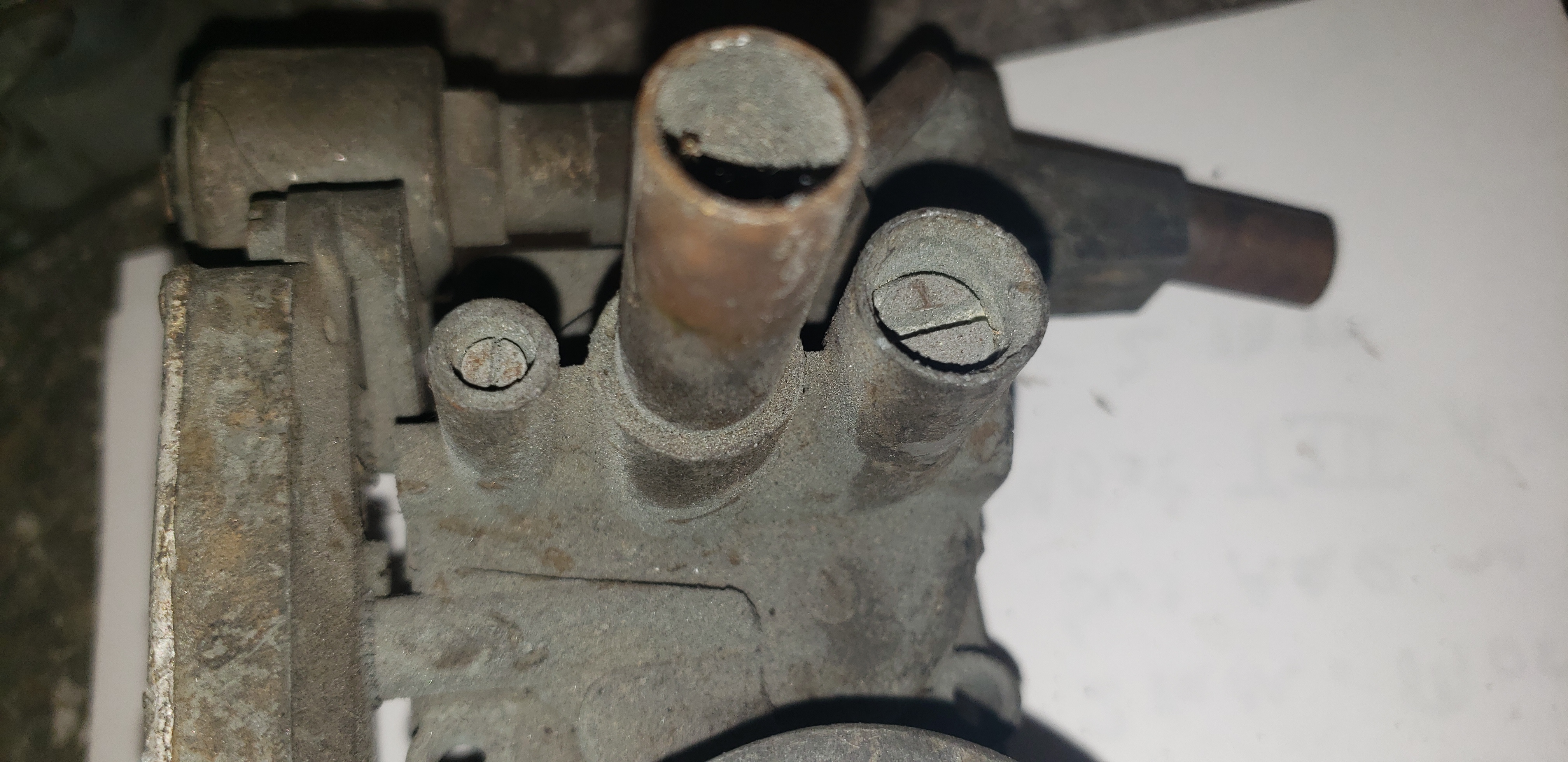
You get rid of two of these objects. The lower object is for idle control – primitive smog. It varies the idle mixture. Type 3’s didn’t have them. Type 4’s don’t need them either. The middle object is the electromagnetic pilot/idle jet (from here on, I’ll call it the pilot jet). The upper object is the idle air cutofff valve. It closes the route to the atmosphere from the third carb when the engine is off to prevent fuel vapor from entering the atmosphere – smog. Type 3s didn’t have them. When finished with this project, the only thing retained in the photo is the idle air cutoff. It won’t be connected. The end can be cut off. But the only purpose it will serve is to plug the hole it screws into. A bolt with the same threads will also work. This is all possible because we’re eliminating the third carb.
Here’s the top of the third carb
and here’s the bottom
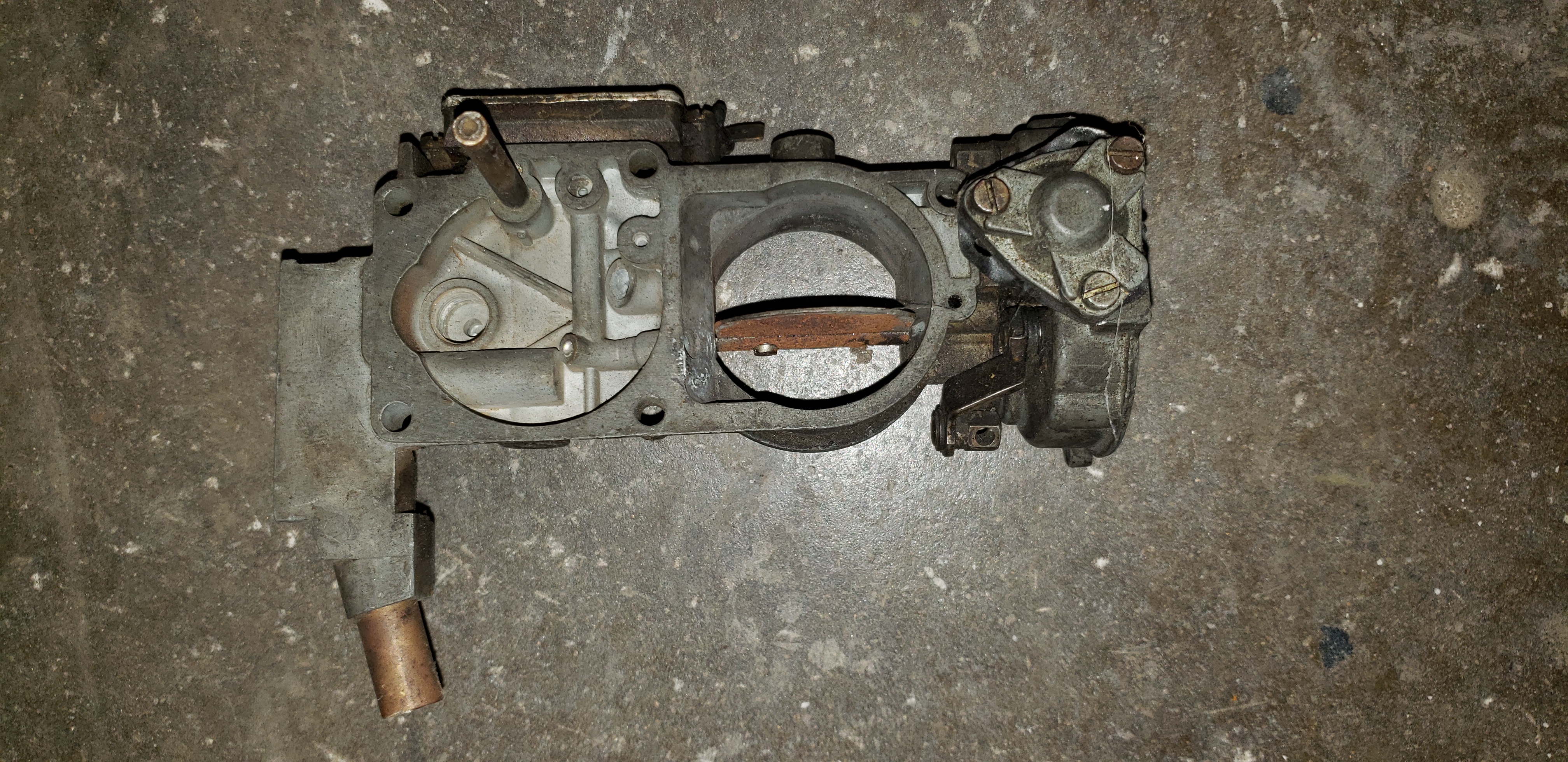
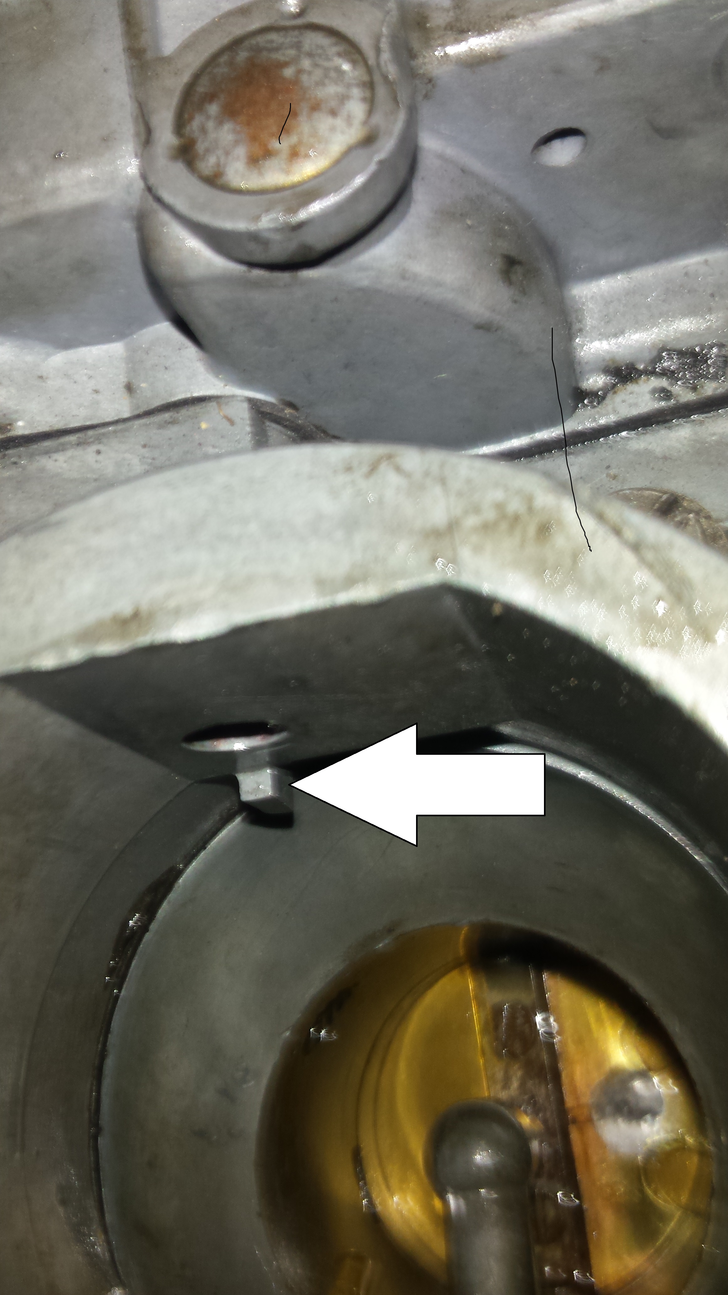
Screw both adjustment screws in the top part all the way in to render them ineffective. The brass third carb fuel pickup tube in the lower pic that reaches to near bottom of the float bowl can be removed or left but removal is better because if it ever falls out it can jam the float. But regardless, it’s rendered useless by this project. It just twists out with a pair of pliers. If removed, the hole it leaves should be plugged with a well peened 1/4 inch set screw. There’ no need to tap threads. The soft aluminum will allow allow the screw to cut it’s own threads as you screw it in.
The reason for doing all this is the gain in reliability and simplicity by getting rid of the numerous wires that attach to various electrical parts of the carbs. These wires tend to fall off or break over time and more than causing an idle problem can cause a fire. Getting rid of the electromagnetic pilot/idle jets is a good thing too. These things are heavy unlike the typical pilot/idle jets. They like to come loose. When they come loose, they hang on the side of the carb and ovalize the hole they screw into. Sometimes they can be tightened back up, sometimes you need another carb if the hole is too messed up. There are inserts designed specifically to fix theses threads when they strip. But this is not a very good fix. Realize that the tip of the pilot jets seats into a small concavity at the bottom of the hole. The jet must be perfectly centered for the tip of the jet to mate perfectly with the concavity and with an insert it probably won’t. Fuel is supposed to flow from downstream of the main jet into the holes on the side of the pilot jet and and out the hole in the end and into the carb idle circuit. If the tip doesn’t center on the concavity, the fuel flows not only through the hole in the jet but between the mating surface at the tip of the jet and the concavity that it mates to. It will never center perfectly with an insert because the insert changes the centering of the pilot jet. This results in poor response when adjusting the idle mixture screw (if it responds at all) and a less that satisfactory idle.
The pilot jet on the left is typical. The one on the right is from and early electromagnetic pilot jet. This early version is removable from the electric part. The hole that used to be occupied by the pin is plugged with small screw so it can be used as a “normal” jet. Both jets are interchangeable as far as fit, but the longer threads can be handy. When a typical bolt is tight, the head of the bolt contacts the surface it’s tightened against. But a pilot jet is tight when it’s tip is seated into the concavity at the bottom of the hole it screws into. It’s pretty much the same type of mating you’ll find in gas fittings for a gas stove in your house. Sometimes the head of the jet will begin to contact the surface of the carb as you’re tightening it. Therefore, the tip will not make proper contact with the concavity and seal. If this happens, do this …
Notice the head of this jet has been tapered in order to obtain clearance at the carb surface to allow the tip of the jet to mate properly with the concavity at the bottom of the hole.
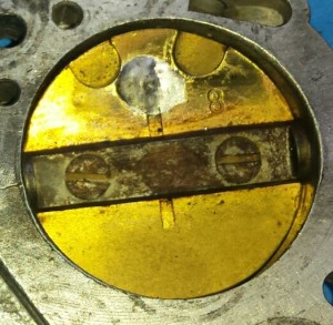
This is a carb with an insert. Likely it had an electromagnetic idle jet that was loose for a long time and the threads needed fixing. But the impossible to perfectly center insert resulted in the tip of the idle jet not centering with the countersink at the bottom of the hole and the orofice itself is damaged too. This resulted in fuel going between the mating surfaces at the tip rather through the hole in the jet and into the carb resulting in to much fuel being delivered making it impossible to obtain a smooth, stable idle. It’ll never happen.
This is a damaged pilot jet hole. It’s damaged because it had an electromagnetic pilot jet hanging from it for a long time. The seat is damaged too. This will never happen with a normal pilot jet. And no wire to fall off either. To be certain the pilot jet seats into the carb, always use a socket or a box end wrench and make it tight so it seats into the carb at the tip. Realized this hole was designed for a very light weight non electromagnetic pilot jet in the early fifties and possibly before WW 2. The significantly heavier electromagnetic jet came along in the sixties and the hole was never changed to compensate for the added weight.
The slower you ride a bicycle, the more perfectly you have to balance. The slower an engine is running, the more perfect the air/fuel ratio has to be. The idle circuit must be perfect for smooth, stable idle and no stumbling when taking off from a stop or, for instance, a slight increase in rpm at slower speeds like when you’re cruising at 40 mph in 4th gear and you push the gas pedal down just a tiny bit to increase speed very slightly.
Throttle bodies, from left to right – 73 and 74, 72 only, and type 3.
Notice there’s no hole in the throttle valve on the type 3 throttle body.
To do this, you need to plug the holes. The 73/74 throttle bodies have
a longer shaft to accommodate the different linkage position found on 72/74
buses to accommodate the plastic air cleaner. You can use type 3
throttle bodies with stock 72 linkage with the 72 only metal oil bath air cleaner. Then you won’t need to bother plugging the flap hole and you get the very cool type 3 adjustment screws.
Washer brazed to repair ovalized hole
The type 4 linkage uses bolts to attach the linkage to the carb top. Use studs to prevent strippage. Any bolt that screws into aluminum is a bad idea cause aluminum likes to strip. Studs reduce this potential to near nothing.
On type 4 buses from 73 and 74 with stock linkage, remove the ball on the right side of the linkage that the rod to the carb attaches to and remount it on the outside of the lever. It comes out just like a rivet – grind the backside off and it’ll pop right out with a punch. Then insert it into the hole from the outside and braze it. Now it’ll never rub on the choke again.
And a Little Bit More
Not responsible for typos or mistatements. If it needs editing, edit it yourself. ( don’t have one. You’ve got a brain. If I say up is down, you should be able to figure it out. Expect few errors. If you gotta brain twister, inebriate yourself, give it a little time. If your light bulb still with go one, send me an email. I’ll answer.
These carbs are superior in every respect to Weber ICT’s which are the typical replacement on type 3’s when someone just can’t get the PDSIT’s to work. The Kadrons are ok but don’t fit on a type 3. They’re very similar with removable venturis, air correction jets and main jets. They’ll give you more power, work much better than ICT’s, but use more gas the the PDSIT’s and I think they’re ugly. And won’t accept any stock VW air cleaner of any kind – paper element or oil bath. ICT’s suck gas, have no removable venturi and the accelerator pump nozzle can’t be adjusted. The fact that it points at the middle of the throttle flap makes for poor atomization thus higher emissions thus contamination of the oil with gasoline. Hesitation is commone, often subtle – they’re kinda soggy coming off idle – low end torque just isn’t that great. The venturi in the middle of the real venturi also delivers and excessive amount of gas. That’s why they work. PDSIT’s don’t have that venturi and don’t need it – they’re designed for a Volkswagen. ICT’s are not. If you switch from ICT’s to the PDSIT’s, you’ll see what I mean. For instance, any stock type 4 engine – 1.7, 1.8 or 2 – liter will will smoothly accelerate with absolutely no hesitation even if you floor it at 15 mph in third gear on a flat road. It’s just like fuel injection without the fuel injection.
Bigger 2 throat Weber’s are great carbs but not practical for a vehicle you plan on using to practical daily driveing or on long excursions. They use lots of gas (less than 10 mpg in town on a 1.8) and are fairly complex. Tiny o rings that are easy to lose just cleaning a pilot jet of which there will be four if you have dual carbs. Each carb has 2 of almost everything else. And they have a lot more potential places to leak fuel than a typical single throat carb so they are a greater fire hazard. PDSIT’s are simple. And if you do everything I’m showing you, they get lot simpler. Very trouble free and easy to deal with should there be a problem and if you do through this whole “ordeal”, there won’t be any problem with them you can’t identify quickly and easily solve.
And realize you get longer engine life from a stock fuel system than a high performance one. For one, less fuel per combustion event means less stress on the engine. Just like the early Porsche 911 – first it was 2 liter. Then 2.2. Then 2.4. Then 2.7. All based on the same framework. When they got to 2.7, problems began to happen. 2 liter was the limit for the type 4 as far as VW was concerned. And you can see it in that the 2 liter cranks don’t hold up like the 1.7 and 1.8’s. Rod journals were smaller in diameter for 2 liter so more pressure per square inch of crank and journal is now a less effective heat sink. The crank and the rod itself don’t really care about the increase in heat. But with more heat at surface due to less effective heat sink function, you get hotter oil and hotter rod bearings. Stroke (leverage – long stroke IS a longer lever. Who was the guy? Atlas, that’s it. His stick broke. That’s why we’re still here.) Longer stroke – more stress on main bearings, especially the split center bearing. I’ve seen a 2 liter crank ready to lose a half peanut size chunk of itself at the center main journal – more leverage and more displacement slamming the crank against the center main = shock on crank. This is why align boring is more often necessary with a 2 liter than a 1.7 or 1.8. 2 liter crank pushes harder on center main. Center main begins to wiggle sooner than if 1.8 f0r instance. Wiggling bearing allows for more flex at crank. Which cause center main to get even looser. And the cylinder walls for a 2 liter are thinner than 1.7 and 1.8. Thus, a weaker cylinder more subject to distortion (result is more oil consumption) and less effective perfect seal (shorter lifespan of a perfect, new engine seal) at cylinder to cylinder head interface. BTY – they start to wiggle the first time you start a new motor. Drive like a (risking being tooled by the evolving daily politically correct as being age and sexually politically incorrect) an old lady, this problem diminishes – geometric vs exponential. The faster you drive, the shorter the life of the engine and life decreases exponentially with speed.
The medal for the absolute worst carburetor to put on any type 4 VW engine is the center mounted progressive carburetor. It’ll run bad, suck gas and ruin the ring grooves in the pistons rather quickly due to the excessive gas they deliver. It remains unburned and thus washes the oil off the cylinder walls and the pistons themselves. Some of this fuel burns, some of it ends up in the oil and some of it ends up in the air – gasoline steam. These are the hydrocarbons that can make a car flunk a smog test. And smog tests aren’t just some arbitrary test. A car that flunks a smog test but runs right has something wrong with it regardless of how well it runs Vodka. You will never get this carb to work right on a type 4 engine. They seem to work ok on bug engines though however I wouldn’t do it.
Due to the washing off of the oil, the piston ring lands (grooves in the pistons for the piston rings) experience very accelerated wear allowing the rings to wiggle and the result is excessive crankcase blowby. Blowby is internal pressure in the crankcase – pressure that want’s to leave the case. The breather hose leading the air cleaner is the vent. The internal pressure pushes air out, into and through this hose and the air flowing through the air cleaner into the engine is sucking it out of the hose – assisting. Whatever comes out of the hose gets burned in the engine. It’s pretty effective. But excessive blowby can’t be compensated by this system because it’s overwhelmed by the additional pressure from the combustion pressure leaking between the rings and the pistons.
What eventually happens is the unheard of except on the Volkswagen type 4 engine – bus or Vanagon. – and that is the excessive blowby begins to force oil mist (realize the environment inside the crankcase of any engine is a literal hurricane of oil) right out the end of the dipstick tube. Even with the dipstick pushed all the way in properly. And the fan sucks it right in. And blows it all over the engine.
That may be the oil leak you can’t find. Now you know where it is.
And this is a very very very common “symptom” of the center mounted progressive carburetor. The center mounted progressive carburetor is also the cheapest fuel system you can by off the shelf for a type 4 engine that’s missing the carbs or the fuel injection. Usually because either the stock carbs or the fuel injection have been deemed junk by the unknowing.
A quick solution is proper carburetion and a new set of Brazilian Mahle’s or AA’s. But the same thing will happen with any stock fuel system – it just takes longer. Because all currently, readily available stock pistons are cast aluminum with cast iron rings – soft and soft. Every new vehicle made comes new with forged pistons and chrome rings. On even the most well built type 4 engine, the cast pistons will bring you excessive blowby long before the valves stop sealing, the lifters wear or the engine’s ready to throw a rod. And excessive fuel consumption will get you there even sooner. So that’s why this topic is under the heading “PDSIT”. That’s part of the solution for long engine life – proper fuel mixture. And forged pistons. That aren’t available anymore. But JE pistons will make stock pistons for you. AA will sell you the cylinders.
You may spend between 800 and 900. So it may cost you about 600 more than a stock set but after all you’ve spent already, what’s another 600? And you’ll get chrome rings instead of iron rings. They last much longer on the cylinder side. And with the long term wear resistant groove of a hard forged piston, they’ll seal for a long time on the piston interface. Realize the ring wears where it touches the cylinder and not at the piston. But the piston wears where it touches the ring. Since the ring is inherently a spring, it’s forever pushing outward on the cylinder – perfect seal. As the piston wears and the rings begin to wiggle, high pressure combustion gases leak between the piston and the wiggling ring and you end up with excessive crankcase pressure and you get blowby and with a type 4 engine you end up with oil coming out of the dipstick. Use forged pistons, do everything else right, and you’ll be leaving your bus to your grand kids, no joke. And if you really wanna go all out, buy a set of used genuine pistons and cylinders. Toss the pistons, have the cylinders bored to 0.020 over and have JE make pistons to match. Now it’s as good as new. As long as you use the Non-Lego Toy method of engine assembly, shown here in excruciating detail …
http://haysvwrepair.com/rebuilding-an-air-cooled-vw-engine-non-lego-toy-style/
Again, the editing disclaimer applies.
Fuel injection is great. But for a trip to the moon, I’d rather use carbs. No electronics. You can fix a carb. With these carbs, for spares bring kits – at least needle valves and accelerator pump diaphragms and maybe floats. They hardly ever leak but they gotta be German (good used). There’s nothing much left to fail. With injection you’ll need a fuel pump, fuel pump relay, computer, air flow sensor (test it first – even a fresh rebuilt one). At least a couple injectors, definitely a head sensor, a cold start valve and maybe a thermo time switch. And a couple extra plugs with leads for the injectors or cold start valve or whatever. A quick fix for a plug that won’t stay on or broken so the metal clip is ineffective can be held with super glue and since super glue brittle, the plug with come out with little effort if need be.
PDSIT carbs are all pretty much the same. VW change the position of the main jet, the size of the pilot jet air bleed, they say the type 3 accelerator pump nozzles are different, all bus throttle bodies have a hole in the throttle flap that type 3’s never had and the casting of the bodies changed along with the idle adjustment screw. But, they’re all bascically the same carb. That’s why they all say PDSIT on them. The Brazilina versions are different in one respect – the emulsion tube. It’s unchangeable so everything here applies to German PDSIT’s. The kind you find at a swap meet. Not new online. Forget that crap. I was told they’re for ethanol. We’re using gasoline here. So …
All PDIST carb tops and bodies (the part with the float bowl) are pretty much the same. The venturis, main jets, air correction jets and idle jets vary but are all interchangeable. Here’s how the throttle bodies vary …
Type 3 has 3 idle ports
Type 4 has 4 idle ports
Here’s how they look on the outside
And here are the 3 different throttle levers 2 bus throttle plates can use either the bus lever or the type 3 lever but the type 3 ball is smaller.
2 bus throttle plates can use either the bus lever or the type 3 lever but the type 3 ball is smaller. The balls are easy to change. They’re a much a rivet as they are a ball in that one can grind the material from the opposite side of the ball, pop the ball out an put another one in since the hole sizes are all the same.
It’s good to know because the right side linkage connection rod is notorious for rubbing on the choke housing on 73 and 74 buses. this is easy to solve – remove the ball and re-insert it from the other side of the linkage arm so it’s like this ….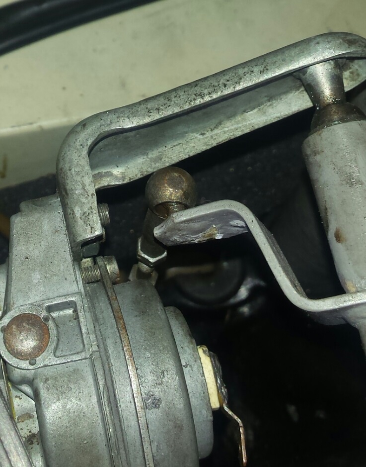
It’s brazed on from the back side now. It’ll never rub again. The left side doesn’t need this kind of attention – it never rubs.
And more old unedited
Even a 2 liter type 4. It’ll run like it’s got fuel injection without the fuel injection.
If you do the full on carb transformation, you’re gonna be busy.
And you should read this first …
http://haysvwrepair.com/how-to-do-a-real-tune-up-on-an-air-cooled-vw/
You’ll really need to read everything below before you begin. If you follow it all the way through and pull if off, I promise amazing results.
And all of the below assumes your engine actually has reasonable compression.
If your not sure or you need engine work, read this …
http://haysvwrepair.com/?s=lego
If you’re past that, here’s the gist …
No more choke wires, no more electromagnetic idle jets failing or falling out or coming loose (which if ignored destroys the soft threads in their respective holes in the carbs), no other wires going to the other odd things found on some type 4 bus carbs, no more vacuum advance unit, no more vacuum hoses, no more very unusual idle adjustment procedure, no more strobe timing light, and if you have it but it’s legal to toss it – no fuel injection which is good because there are no new genuine Bosch fuel injection parts manufactured anymore – particularly the air flow sensor (rebuilt ones are a crap shoot) and the head sensor. Nice and simple. And it’ll run better.
You can use any distributor you want (almost – I’ve never tried a vacuum only distributor although many type 3’s that came stock with these carbs came with vacuum only except for the 1500 S. The main advantage to a mechanical only distributor is there’s no rubber diaphragm to ever leak. A vehicle with a vacuum only distributor with a broken diaphragm will barely move. With a 2 hose advance, you’ll need plug the retard hose, and leave the advance hose connected. The vehicle will run pretty good even if the advance side is toast because the mechanical advance is still present. They actually run pretty good like that. You set the timing at 10 advanced. 009’s, 019’s, a fuel injected type 3 distributor they’ll all work. Any distributor that has a mechanical advance will work and you’ll have proper idle speed. Different distributors have different advance curves which affects acceleration, but regardless, you’ll be able to set a proper idle speed.
This is what’s going on with the carbs that come on buses from 72 thru 74 … They’re designed to run with the timing set at 5 before top dead center at idle. Imagine the bus brand new and all stock. It runs perfectly and the timing is correctly set at 5 degrees after top dead center. It’s idling and you’re standing behind it. Suddenly, the retard side of the diaphragm ruptures. At that moment, the timing will jump to about 10 degrees after top dead center – advanced. As soon as this happens, the idle speed will go up with it. It’s just the nature of engines – when you advance the timing, the idle speed goes up.
Unaware of the failed retard diaphragm in the bus, one might attempt to turn down the idle speed using the speed screw (air screw from now on) at the top of the left carb and find that with the air screw all the way in, the idle has gotten lower but it’s still too high. Messing with the throttle stop adjusting screws at the throttle bodies wouldn’t drop the speed anything more that a minuscule amount if any.
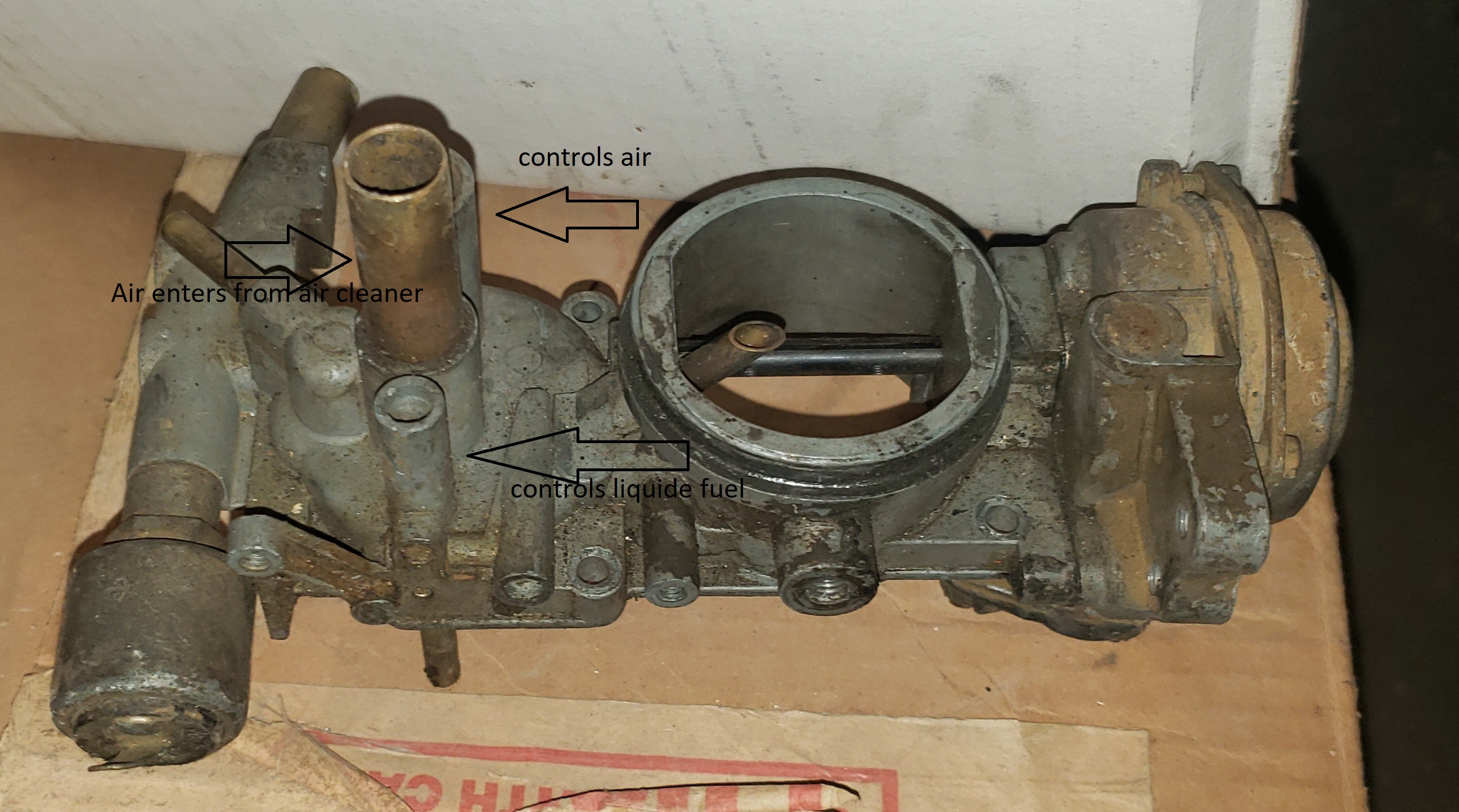
Realize that increasing the idle speed on any VW carb designed without an a air screw, but with clockwise rotation of the throttle stop screw for the purpose of speed adjustment (all original carbs on any model prior to 1968 did not have an air screw, only throttle stop screws and strictly for speed adjustment) simply results in allowing more air to come in past the throttle valve (the flap). Even when the screw is backed all the way out and the flap is as closed as possible, one can still see daylight passing through the gap around much of the flap. Air passes through this gap when the engine is idling. The stop screw allows you to increase the amount of air and thus the idle speed. Liquid fuel supplied by the pilot (idle jet) which is fed fuel by and located downstream from the main jet, is partially atomized within the body of the carb with air passing through the pilot jet air bleed. This atomized fuel mixture is introduced into the air stream passing through the gap at the flap through several small holes (ports from now on) in the bore right next to the idle mixture screw. The farther you open the flap, the more air there is available pulling idle fuel mixture into the air stream headed for the engine.
The outlet ports must be located not far away from the typical idle position of the flap to take advantage of the fast moving air passing between the flap and the bore of the carb to draw fuel from the idle circuit. Typical idle mixture adjustment is carried out by screwing the mixture screw in until the engine begins to sputter, the screwing it back out until the idle is smooth. If the flaps too far open, there would be no response to the mixture screw. That’s why the Bentley Book instructs you to measure the gap with a feeler gauge and perform the actual speed and mixture adjustment at the 3rd carburetor.
I know this all sounds very convoluted if not complicated, but the thing is this. The reason VW and many other car manufacturers changed idle timing to 5 degrees after top dead center is to decrease the emissions of hydrocarbons at idle. But since the retarded timing reduced the idle speed so much the vehicle wouldn’t idle properly, they put a hole in the throttle flap of the bus carbs. This gives the engine more air for a higher idle without having to adjust the speed screw on the throttle body. Thus, stock type 4 bus carb throttle bodies are adjusted with a gauge to a real small gap and the hole provides the proper amount of air for the mixture screws in the throttle body. Since injected type 3’s had the timing set at zero, you won’t find this hole in the throttle flap nor will find it in t 3 carbureted throttle bodies. You will find this hole in every fuel injected bus or air cooled Vanagon (not sure on water cooled vanagon) that has a 2 hose distributor with the timing set a 5 degrees after top dead center. If you find yourself going nuts with a Vanagon with a high idle speed you can’t fix, take a look at the throttle body. Maybe is has one with a hole that shouldn’t have a hole.
That’s why if you put a 009 distributor with the timing set at the correct 10 degrees advanced in a stock carbureted type 4 bus, you’ll never get the idle low enough. For this project, the solution is easy. Solder the hole shut. That’s step one. Then adjust the carbs like a type 3 or ICT’s or big Webers – typical mixture and speed screws.
No more 3rd carb ….
The air screw on the 3rd carb (it’s built into the rear of the left carb 0n a 72 bus for instance) controls the amount of air available to the fuel that’s drawn up the tube that reaches from the carb top to the bottom of the float bowl. Fuel mixes with this air and is fed to the pipe that is mated to the right side of the passenger side intake manifold and the left side of the driver’s side manifold. The mixture screw and air screw actually compose this third carb that’s strictly for idle with a single tiny fuel jet (tiny hole at the bottom of the pipe that leads to the bottom of reservoir) and and adjustable air jet – the air screw. The air jet offers variable control of the air to mix with the fuel from the reservoir pipe to arrive at the proper idle speed. But it’s only got so much range of adjustment. It’s the proper range for a vehicle that requires the timing to be set at 5 degrees before top dead center and can’t compensate for idle speed that’s been cranked up because the timing is set 15 degrees (that’s 10 degrees before top dead center – advanced. 10 advanced past zero plus 5 before the zero = 15 degrees difference) further advanced from where it’s supposed to be. 15 degrees makes a huge difference in idle speed.
If you look at the throttle valve (the flap in the throttle body), you’ll notice there’s a hole in it. All VW’s with the engine in the back with the vacuum retard feature that requires the timing to be set at 5 or even 10 degrees (some buses) have a hole in this flap. Even fuel injected Vanagons. They may not have carbs, but they have throttle bodies and they have the hole.
VW vehicles designed with no vacuum retard feature do not have this hole.
This hole is the reason it’s impossible to properly adjust the idle speed on 5 degree retarded bus when the timing is set to 10 advanced, for instance with a 009 distributor. It’s because engines run on air and gas and the hole provides to much air. And turning the air screw all the way isn’t enough.
To make is possible to set the proper idle speed, using the throttle stop screws at the throttle body, here’s the requirements:
Solder the hole shut. Simple, no?
Screw the mixture and air screws for the third carb all the way in
Disconnect the wire for the big electromagnetic idle air shut off valve and tape or cut it off entirely (recommended). You can even screw the proper size bolt into the hole.
Plugging this hose from within is a good idea. If the valve ever falls out, you won’t even know it. The rest of the pipe acts like a typical balance tube found on many dual carb set ups.
Drill the pilot jet air bleed hole to 2 millimeters. The stock bus size is about 1.5 millimeters.
That’s it.
The easy way if you have a 72-74 bus with stock carbs and it. runs ok with the carbs that are on it but if you want it to run better or you need a vacuum advance/retard unit because the retard side of yours leaks and you can’t find a new one and a used one might fail quickly or you have a distributor that requires the timins dle is too high with the idle air screw and mixture screw on top of the left carb all the way in ..tomorrow. In that case you can set the timing statically at 10 degrees advanced ((strobe not recommended in this condition because idle speed too high without retard working (until you do what’s shown below) so you get an inaccurate reading but you’ll never get the idle down to where it’s supposed to be unless you do the following …
Remove the carbs and solder the holes in each throttle flap closed. Here’s the hole soldered shut. Solder from both sides so there’s no way it’ll fall out so you won’t have to do it again, not so it won’t hurt the motor because it won’t. It’s just too soft. It’ll end up on the highway after it passes out the tailpipe just like that missing nozzle. That’s why the nozzle is brass – it can’t hurt the engine if it falls in. An alternative may be a tiny brass screw and nut that are so well peened they’re unrecognizable and tight – nearly flat. Just be careful not to distort the throttle plate when using a hammer for peening. Slight distortion can cause binding. I’ve never used that method, only solder. I used a “Mini Torch” oxy acetylene welding set up to solder. A modern flame type soldering tool may work. A butane cigarette torch type lighter may work. You probably won’t be able to get the area hot enough with a typical soldering gun for an effective bond.
Drill the each idle air bleed jet out to 2 millimeters. Here’s a pic. This is permanent. You can’t go back but as far as I’m concerned, there’s no reason unless you have a spare dual vacuum units with a non leaking retard side. That’s the side that connects to the driver’s side throttle body. The retard pipe on the vacuum unit points toward the distributor and it’s a tiny bit bigger than the advance pipe on the vacuum unit.
Remove the choke flap – it’s the choke flap that almost invariably causes the accelerator pump nozzles to fall out or shear off ( choke flap removal is not necessary for this but they don’t make nozzles anymore and it sucks when they fall out. Sometimes they shear and it’s not impossible to mess up the hole in the carb for the nozzle with inexperienced hands trying to remove the remnant from a sheared nozzle. Messed up holes can’t be fixed.
The reason the choke flap is an effective nozzle killing machine is because there’s a stop for it to prevent it from going past perfectly vertical as it should be in fully warmed up position. The stop is often broken and since the nozzle is so close the the choke flap, the nozzle becomes the new stop. The arrow points to the stop in the pic …
You’ll need a screwdriver that engages deeply and firmly into the choke flap screws if you ever intend to put it back in. You may need a little heat. You may need to grind the peened tip of the screw to it can travel through the choke shaft. Above all, it you ever intend to use the chokes again, you must not distort the shaft. If you bend it the tiniest amount, the choke will bind and you may, as a last resort, need to drill the bronze bushing it rotates in that’s hidden within the choke housing – fragile, spring like lint that’s easy to damage, time consuming, tricky, work. You just need to drill the bushing a teensy bit bigger. Works on bug carbs too.
To remove a damaged or sheared off nozzle, make sure there is zero gasoline left in the carb and none in the area you’re working in. Here’s how you do it …
Heat the surrounding area lightly and gently for a few moments with a torch. Use the outer part of the flame where it’s not so hot. Just wave it lightly like your brushing the area with a feather. If there’s enough remnant nozzle, pliers should remove it. If it’s sheared off, use an easy out or try to engage a tiny self tapping screw and remove with pliers.
Peen the nozzles when installing. They’ll never fall out and without the choke flap, they’ll never shear. A smaller, narrow, pointy center punch is good for this but an ice pick will work or even a nail. File a nail to a nice sharp point then hit the tip with the file so it’s not sharp like a needle. Don’t let your tool touch the nozzle itself unless it rotates. Always peen at the interface where the collar meets the carb itself. When finished, make sure nozzle does not rotate within collar. Use pliers … gently … to check. Another reason to not use the Brazilian renditions – I’ve had some where it’s virtually impossible to keep the nozzle from turning within the collar even when peened all over the place with a large flagpole sharpened in a large flagpole/pencil sharpener. I just wouldn’t happen. If a nozzle rotates. you’ll have to peen at the nozzle to collar interface but only after being certain that collar/carb interface peening won’t do it.
Aim the nozzles
The short length of rubber hose leading from the back side of the left carb to the metal pipe that leads to outside of each manifold – plug it internally between the carb and the pipe. It’s in the big one with hose clamps in this pic …
Reinstall carbs
Plug the vacuum retard port on the throttle body of the left carburetor.
Screw the air screw and the mixture screw on the back side of the left carb all the way in
Disconnect and tape or cut the wire for the big air jet that screws into rear of the left carb
If you have a 2 hose – vacuum advance and retard distributor – set the timing at 10 degrees advanced – the retard hose is disabled (port plugged previously). If you use strobe timing light, disconnect the advance hose when setting the timing. If you’re doing static timing, the hose can stay on.
If you have a mechanical only distributor set to 10 degrees advanced.
If you have any other distributor, set the timing per specs for that distributor but any VW distributor with mechanical advance will work. Invariably, any original VW mechanical distributor that has as single port unit must be set at zero. Early fuel injected type 3 for instance. However, if you’re using a 36 hp distributor, 7.5 is where you’d set it. I don’t know how it would run with one, but that’s where you’d set the timing for one of those. Vacuum only? Haven’t tried it. 009 and 010 is recommended – no rubber to break … ever. 009 works great
Now you adjust idle speed with the throttle stop screws on the throttle bodies. You’ll also be using the mixture screws on the throttle bodies for mixture adjustment. It’ll run great. Idle when cold. And start without chokes even in the twenties. Worried about cold starting? Bring starting fluid. Or put the choke flaps back in every winter. But I know it’ll work without ’em. I’d never suggest you do anything I haven’t tried myself … Idaho, Minnesota – November. Check.
The Hard Way including if you have no carbs or you wish to put carburetors on your VW that were actually designed specifically for a VW engine and wanna do a real nice job ….
Carb tops must be from any year type 4 buses – left and right – if you wish to use the stock bus linkage which requires the use of the stock bus air cleaner.
72 uses an oil bath air cleaner. 73 and 74 are the same – plastic with a paper element.
This is a 73 and 74 set up …
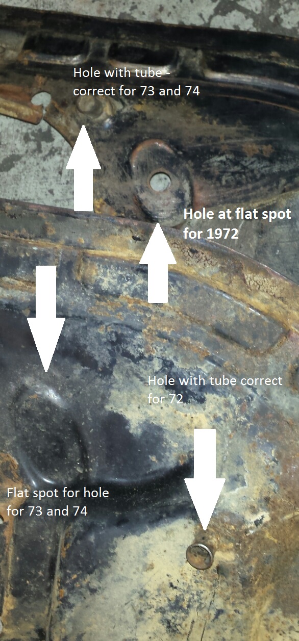
The hole in the front engine sheet metal for the accelerator cable is in one place for a 72 and another for 73 and 74
You can use type 3 carbs but you’ll need the typical chrome aftermarket air cleaners. You’ll need to break off the original air cleaner mounting bracket from the top of the carb so these air cleaners will fit. Early 36 hp engine air cleaners will work too. If you have lots of room like in a Ghia or a bus, you can use pretty much any air cleaner for any air cooled VW if you’ve got room for it. 65 bug air cleaners will even fit. You get the picture.
If you use the type 3 carbs, you’ll need a center pull linkage. Ignore the bad press regarding this linkage. This is s a very simple linkage compared to the so-called Porsche style linkage. Porsche style and Porsche quality and function are 2 different things.
The the grooves for seal where the air cleaner mates with the 72 carb tops are different from the 73 and 74’s but a thermostat o ring for a water cooled car will work – I don’t know which car – but the product you need is Stant part number 25269. Stant is a manufacturer of water cooled automobile parts. With this part number you should be able to pick it up at most auto parts stores however, the part number may cross reference to another manufacturer. If this is the case, even though the application is the same and the seal is theoretically the same, it may not work – too tight; too thick; whatever …. therefore, you’ll may have to get the seal specifically made by Stant because I know it’ll work and every single one should be exactly what I got because they’re made by the same company as the ones I know that work – Stant.
There’s two kinds of clip used that hold down the snouts that lead to the carbs for stock bus air cleaners – short for the 72 and long for the 73 and 74. Left and right are the same. The attachment hole position on the carb tops is in the same on all type 4 bus carbs.
The stands the air cleaner sits on – short for 72 and long for 73 and 74. Left and right are the same.
72 only linkage or 73-74 linkage dependent on the air cleaner you wish to use. You’ll need the corresponding parts that the cross bar engages with at the carbs – left and right. You’ll also need the rods the reach from the linkage ends to the levers on the carbs. The right side is adjustable. The left is not.
Carb bodies – the the middle part (part with float bowl) from any type 3 or bus. Type 3 carbs have the main jet access plug facing the middle of the engine. They bus carbs have the plug on the front of the bus. The type 3 configuration provides the least awkward access to the plug so if you can, use type 3 bodies. You’ll appreciate this when it comes time to determininethe best main jet size for your application but it’s not essential and bus carbs are plentiful. But whether you use type 3 or bus, they must be German for best performance. Brazilian will work but you will not get the maximum rpm the engine is capable of in stock form. As an example, a 67 bus with stock trans and stock single port will do 50 mph in third gear with these carbs. With Brazilian bodies it’ll only do 40 mph. Fact. Under no means assume that buying a new PDSIT kit will achieve the same thing as the using my method, you will not. You’ll get far less. If they even work at all. For one thing, they come with a very small venturi. I’m told they’re designed for use with ethanol, found in Brazilian gas stations but not here. Follow all these steps and you’ll get the most out of any stock type 4 engine from 1700 to 2000.
You can use any throttle bodies (the part with the flap or butterfly) – Brazilian or otherwise. There are at least 2 different bore diameters. Ignore the diameter. The largest bore throttle body is the bus type. It’s a little bigger than the type 3 body and the type 3 body is the same diameter is the same as the bore of the carb. The bus body is a little bigger than the bore. The bore of the carb is the diameter of the hole the venturi slides into. That’s where the 34 comes from in 34 PDSIT. So the bore is really the size of the the widest part of the venturi.
Since the carbs are all the same bore and the throttle bodies vary, apparently it doesn’t matter (and it doesn’t, I’ve tried it both ways) which throttle body you use but the idle ports on the type 3 body are bigger than type 4. Type 4 has smaller holes but there’s more of them. The larger diameter of the bore is likely a requirement for proper idle/timing function with the stock setup for 72 to 74 buses with the original vacuum unit with vacuum retard (2 places to connect a hose – one for vacuum advance and one for vacuum retard) connected via vacuum hose to the left side throttle body) which is no longer available from Bosch. I believe the current Brazilian version has a larger bore also. But regarding the vacuum retard type vacuum unit – since the vacuum unit has rubber inside, any used unit is … old, and prone to failure. With this modification, you’ll never need another vacuum unit with the retard “feature”.
Let’s start with the throttle bodies. Buses from 72 to 74 had a 2 hose vacuum unit. The hose fitting that faces the distributor is the vacuum retard hose. The other hose is the vacuum advance hose. The retard hose maintains the timing while idling at 5 degrees retarded. Now, if you have any air cooled V W running at idle and advance the timing by rotating distributor clockwise while running, the idle speed with go up. Rotating the distributor counterclockwise will retard the timing and the idle speed will go down.
Buses with this 2 hose distributor have a small hole (3 or 4 millimeters?) in the throttle body flap. You’ll need to solder this hole closed. Solder from both sides to prevent the solder from falling out – overlap the edges, don’t just fill the hole. And realize that if the solder falls out, it will not hurt the engine. It’s soft; it’ll just blow out the exhaust.
The hole is there to give the engine more air for a proper idle speed adjustment. More air – higher potential idle speed. Has the same effect as turning in the speed screw thus increasing the size of the gap between the flap and the side of the throttle body – more air, higher idle. The hole in the flap allows for high enough idle speed with the timing at 5 degrees retarded. It supplies the extra air needed for proper idle mixture. Without the hole, the flap would have to be adjusted so far open via the adjustment screw, it would be on too high of an angle to line up properly with the tiny holes next to it’s edge that supply fuel at idle. The reason for all this is because …
the real idle speed adjustment for the bus carb is the air screw at the back side (towards front of bus) of the left carb. If you look in the Bentley book, you’ll see there’s a specific gap for the throttle valve. The gap allows the proper amount of air to pass the flap for idle when added to the air coming through the hole you need to plug with solder. Theoretically, once you’ve adjusted the gap, you never touch that adjustment screw again. After the hole is plugged with solder and you do all the following and you’re ready to start it up, you’ll be screwing the air screw at the back of the left carb all the way in, turning it’s mixture screw all the way in and screwing the electric air valve in – working or not, connected or not – it just has to plug the hole. You’ll also use the adjustment screw for the aforementioned gap adjustment to adjust the idle speed as you would on a “normal” carburetor.
Turning the just previously mentioned screws is is … just because they’re there. Because we’re gonna plug this hose from within with a cut off bolt or a stud. It must seal perfectly for a long time.
Here’s the entire plumbing and carbs on a 73 an 74 system. 72 is pretty much the same but since the manifolds are shorter, metal pipes are different. As the type 4 carbureted buses come originally, the pipe with the arrows pointing to the plugged hose carries fuel mixture generated with the fuel that gets draw up the tube that reaches towards the bottom of the float bowl on the left carburetor. It’s completely disabled now so the tube gets removed. Now the pipe is simply a balance tube. The other pipe is also and always was a balance tube. They run fine with both tubes there and open. Just plug the hose where it comes outta the left carb top as previously stated.
Here’s the engine. The pipe we plugged is different for long manifold engines (73 and 74) because it reaches higher to the idle circuit pipe on the left carb and it’s attachment on the air cleaner supports is higher since the supports are longer and reach higher. The 72 bus pipe is different in those respects but looks pretty much just like the one in the pic. The front pipe at the “firewall” is the same for all years except the outlet for the brake server varies from left to right. I don’t know the details here. Worst case is you’ll need a longer hose to reach over to the passenger side of the vehicle if your original hose seems like it probably connected to the left side.
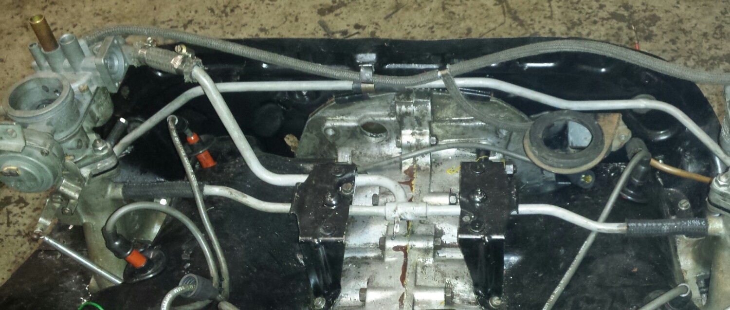
And here’s the tube that used to suck gas outta the bowl for the original idle circuit which worke in conjunction with the one that runs off the pilot jets on the sides of the carbs which is what were gonna end up using for our entire idle circuit. So pull out the tube and after you do that, you’ll see another tiny one under it. Take that one out too. The only reason were taking them out is just in case the come loose and fall out – they can’t, because they’re gone. There’s no reason to have anything in the float bowl that doesn’t need to be there that may fall out and cause a running problem on that long, long journey to Saturn.

If you use type 3 throttle bodies, there’s no hole to solder but you can only use these if you’re using a 72 bus only carburetor system. 73 and 74 buses have a different air cleaner and a different linkage. The throttle lever (it’s held on to the throttle shaft by an 11 mm nut with a lock plates) on models with this type of air cleaner and linkage reaches out much farther measured from the center to the throttle flap to the surface at the end of the lever where the ball is that engages with it’s corresponding linkage rod. This is necessary to clear the air cleaner. The bosses for the throttle shafts are much longer for the increase reach needed for the ball to properly engage with the linkage rods
So for 73 and 74 linkage and air cleaner you’ll have to use the 73 and 74 throttle bodies. Using type 3 throttle bodies is possible but you’ll have to lengthen the levers. It’s a hassle. Offset is different on each side. Here’s a pic. Oh, and it’s a hassle.

Here’s the hole soldered shut. Solder from both side for best result. Alternatives are brazing or using a brass screw and nut that are so well peened they’re unrecognizable – nearly flat and maybe a little solder. Just be careful not to distort the throttle plate when using a hammer for peening. Slight distortion can cause binding. I used a “Mini Torch” with oxy acetylene to solder. A modern flame type soldering tool may work. Or ask a meth addict. They’ve usually got a butane lighter blowtorch in a pocket or purse. You probably won’t be able to get the area hot enough with a typical soldering gun for an effective bond.
German floats. Brazilian ones that come with the Brazilian PDSIT kits available now commonly leak. German ones seldom do. Bus floats are shorter than type 3 floats. A bus float will work in a type 3 body but a type 3 float will hit the bottom of a bus body because the configuration of the bottom of a bus float bowl is different. The type 3 float is on the right; the bus float is on the left.
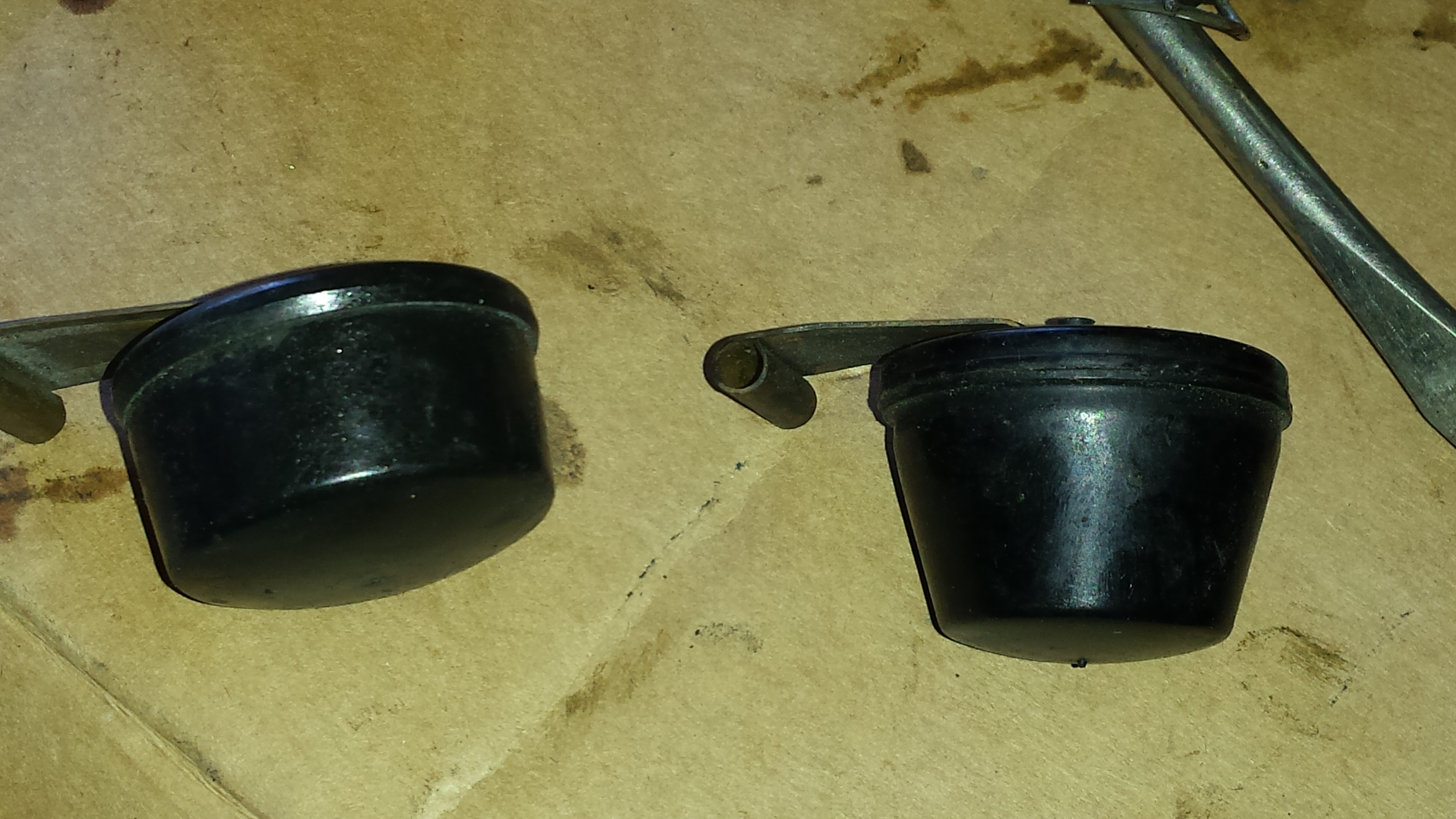
This is the bottom of a bus float bowl. The long type 3 float will hit the edges of the trough. You can use the bus floats in a type 3 bottom however.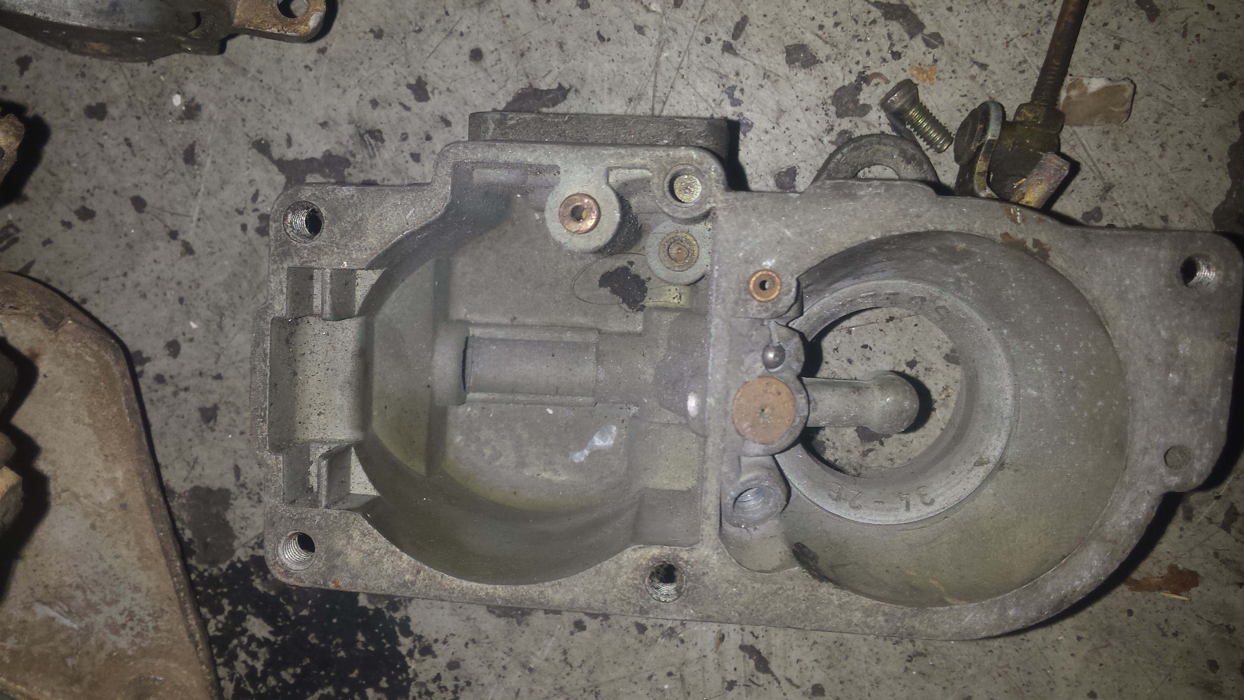
You’ll need to plug this hole for any body you use. It’s a vacuum supply port for the choke pull 0ff. We won’t be using any chokes. Chokes are the reason the accelerator pump nozzles break off in PDSIT carbs. The hole can be jammed with solder. Just keep pounding it in till it’s tight. File it flat.
The arrow in the photo below points to the stop for the choke flap. It keeps the choke flap from going beyond vertical when in hot position. What happens is the stop breaks. Then the accelerator pump nozzle becomes the stop for the choke flap. Eventually the nozzle breaks. It can be very hard to remove the remnant. Don’t mangle the hole or you’ll render the top part of the carb useless. Use an easy out – the biggest one possible. Grind the tip down for a bigger bite if necessary. Heat the surrounding area with a torch. Likely you’ll get it out but realize that heat will probably be necessary if not good insurance against failure. Regardless, this is why we get rid of the choke entirely. Car will still start in real cold weather – Idaho in mid-November for sure. In fact, in real cold weather, the thing to be concerned about is slow cranking speed due to a cold battery. If you live in an arctic climate, use starting fluid for a no-start condition where you think you need chokes. But forget the chokes. Gut everything mentioned previously. Use the paper gasket between the choke element and the carb body and the triangular diaphragm for the choke pull off. Both must be there simply to act as gaskets and prevent metal to metal rubbing – things will stay attached longer with the paper gasket and the diaphragm still in place. You can wire the chokes if you want but just for looks – use a dead wire. We won’t be using any electric jets either – particularly the pilot jets unless you want them there for an authentic look but the thing about these jets is that they come loose and wiggle in the hole. This can damage the threads and make the carb body unusable. The big electromagnetic air jet on the back side of the left carb (bus, not found on type 3) plugs the hole real well and when properly tightened doesn’t tend to come loose and since we’re disabling the system it controls the air for, it really doesn’t need to even be there but I put it in anyway. You can run a dead wire to it for authenticity. You can also use a bolt to fill the hole if you can find one or just tap for a different thread.
The choke mechanism – the shaft and all moving parts found under the electric choke element are removed – everything you see in the pic below. We need only the housing and the screws that secure it. The housing remains because that’s what the bus linkage attaches too. It attaches with 2 bolts. The holes are prone to stripping. Best thing is to install helicoils and studs. This will reduce the chances of stripping to near zero. Realize the linkage puts a lotta stress on the bolts. They tend to come loose – asking for tightening occasionally. Studs with nuts seldom ask and when they do, they’re probably not gonna strip. Worst case is the nuts you’ll be using on them may strip. With a quality – black colored metal vs cheap white stuff – stud, the nut will be the offender. The sump studs from a bug case are a good choice but look in an auto parts store too. But remember – not white metal. Too soft
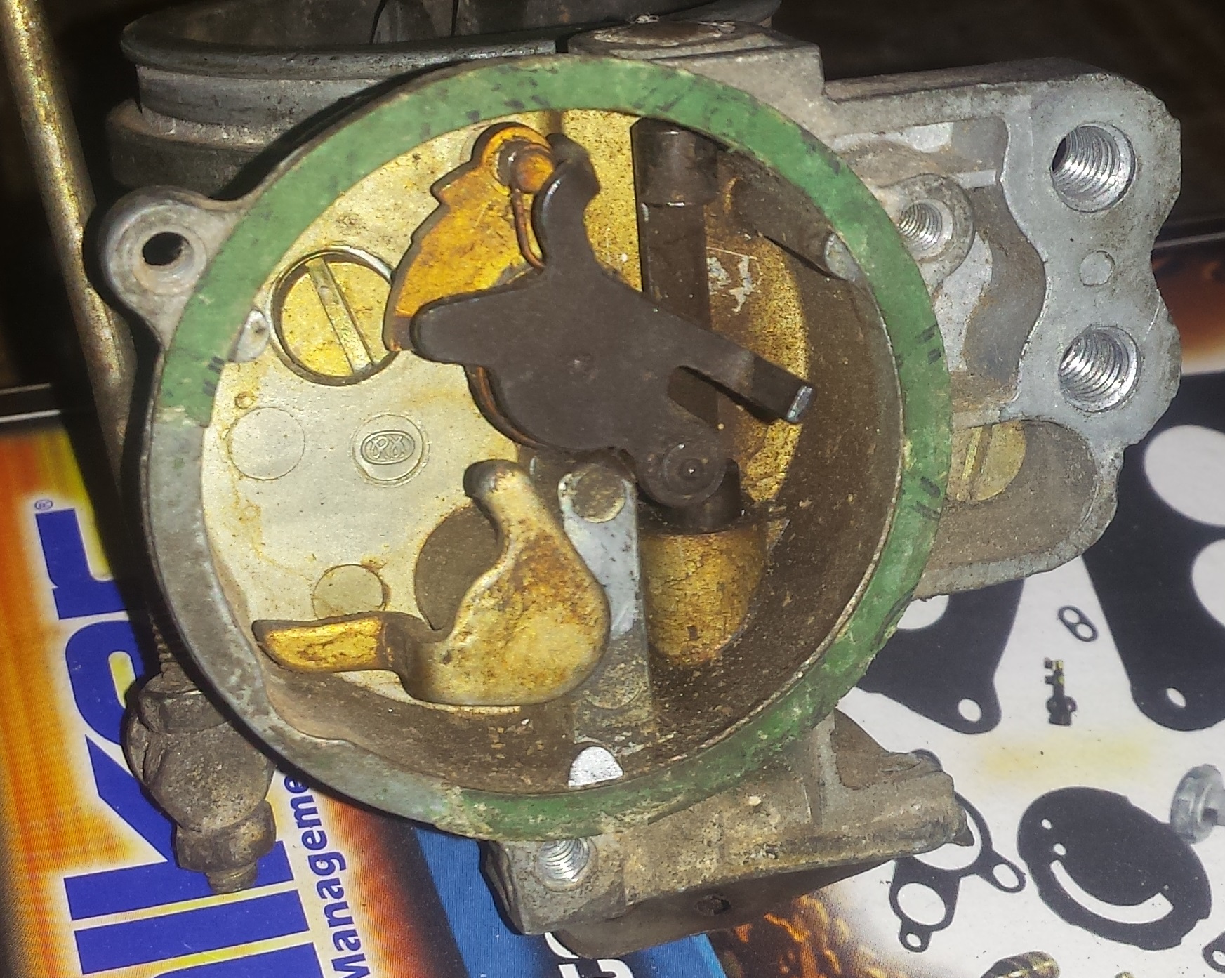 yCa
yCa
Use 1/4 inch allen set screws to plug the choke shaft holes. They’ll screw in without tapping. Screw the one closest to you in the pic from the outside of the carb. Screw the other one in from the inside and peen it well so it’s impossible to fall out.
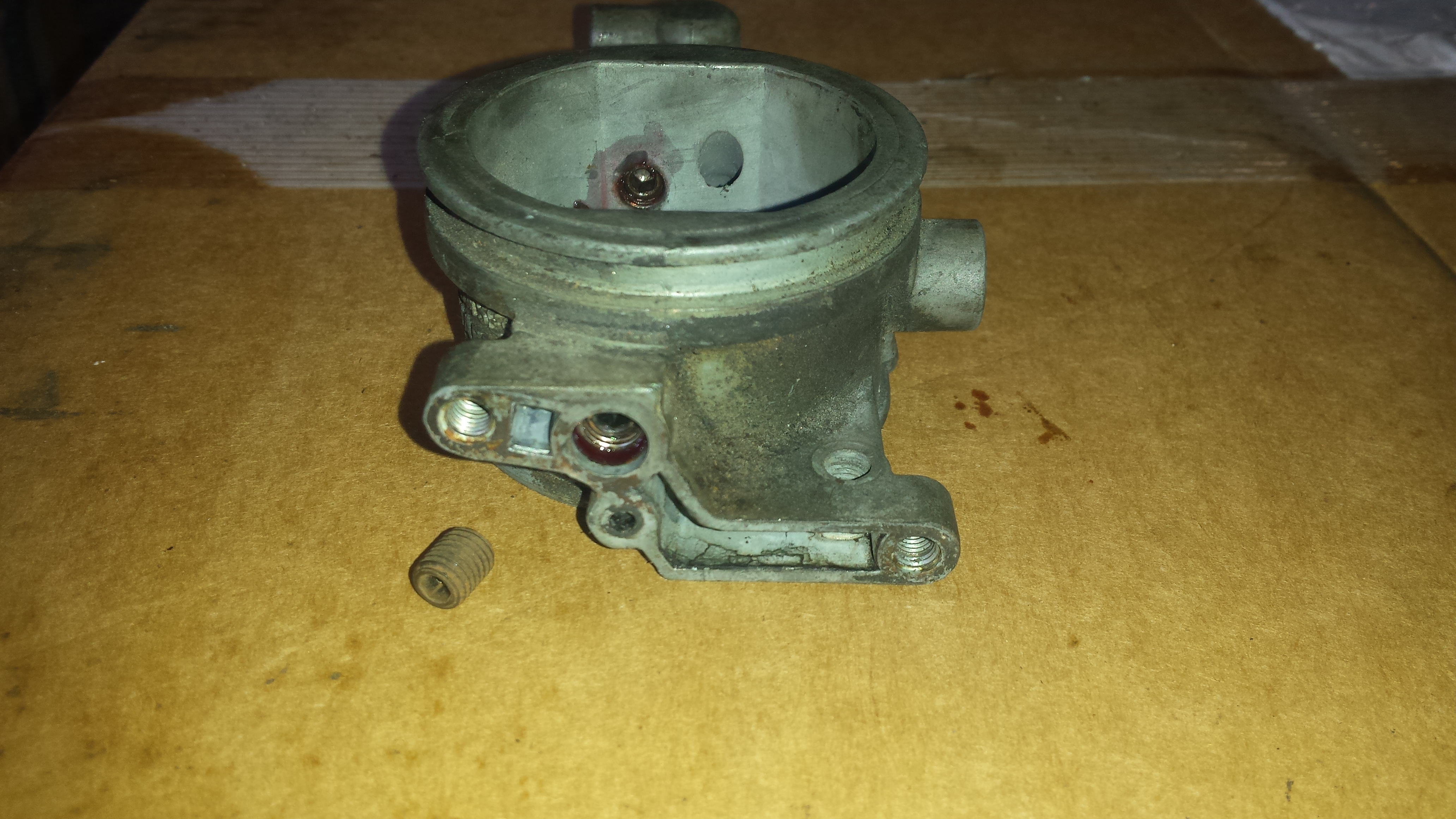
But basically, the whole idea here is to make everything as simple as possible and as safe as possible – everything mechanical with no electricity needed and thus no wires to break or fall off. The only wire you’ll end up with is the one that powers the coil and the one that leads from the coil to the back up lights. And the condenser, of course. That’s it.
If you use bus carb bodies, as shown in the pic below, you’ll need to drill the idle air bleed jet a little bigger. It’s about 1.5 mm in a bus carb. Type 3 carbs are 2 mm. You need to drill it to 2 mm for all this to work. I promise – it really works. Took a long time to figure it all out. Donations gladly accepted. The idle air bleed is really the air correction jet for the idle jet – the pilot jet.
Now the accelerator pump. Forget about everything you read in the book regarding volume. You’ll need to make sure both ball check valves are present and working along with the accelerator pump diaphragm assembly. The main jet plug must be installed but don’t connect the lever to the rod coming off the throttle body. Put gasoline or solvent in the the float bowl. Water or alcohol won’w work because the surface tension of both it too high. They don’t have the properties to squirt properly and realize one drop of water in a carb will block a main jet as effectively as a grain of sand. Anyway, with about an inch of gas or solvent in the bowl, operate the lever at the carb. Your chosen fluid should squirt like this …
The Bentley book goes into detail about the volume of fuel squirted out the accelerator pump nozzle and it’s adjustable by moving the cotter pin from hole to hole at the actuating lever that connects the accelerator pump lever to the throttle body. But the thing is, since every engine is different and each side of every engine is different, you may find that one side of the engine doesn’t even need any fuel from the accelerator pump to run fine. So install the carb top with a gasket and with the actuating rod and place the cotter pin installed, count how long the fuel squirts out of the nozzle … one thousand one, one thousand two, one thousand three …. For me, running out of fuel just before I say “one thousand two” is just enough.
But you my find there’s not enough adjustment to get there – you’re getting too much fuel and you can’t reduce the volume. The only solution is an accelerator pump diaphragm with a longer shaft or a longer actuating lever. I think the carb kits for the Brazilian PDSIT’s come with longer shaft diaphragms than the typical type 3 and bus kits. And they’re likely to be real Solex parts. CB may have them but about the only thing you’ll be able to use from the kit are the diaphragms. The other solution is to make the actuating lever’s longer by about 4 or 5 millimeters. Cut, spread and join with steel tube then braze. After installing the lengthened actuating rod, install cotter pin with the one necessary washer between it and the accelerator pump lever. If you get zero gas per stroke like this, adding washers will increase the volume. Oh, and for ease of adjustment, instead of a cotter pin, use a couple inch long piece of mechanics wire or the hairpin type clip found in most auto parts stores – easy to put on and easy to take off. For me, typical volume is right before I get to one thousand and two. Adjustment for maximum fuel is potentially as much as you see coming out in the video. That’s way too much. You may find the vehicle runs right with some particular volume but here’s a test – coasting down a hill at about 60 mph, let off on the gas pedal for a few seconds then floor it. If you feel a delay, you’re getting too much fuel from the accelerator pump. This is called a rich dump. Also realize the diaphragm stops pushing fuel long before you reach full throttle. Driving at a constant speed at about ten miles per hour in second in a parking lot where you’re likely at less than full throw at the diaphragm, push the pedal down about an inch. If the vehicle bucks, increase the volume. One washer might be enough. Realize the vehicle may not hesitate taking off in any gear but at rather low to mid-range rpm and fairly low speeds, you my encounter the previous. That’s what the parking lot test is for.
Short manifolds give high end; long manifolds give more low end
Why …These carbs are superior in every respect to Weber ICT’s. The Kadrons are ok and very similar with removable venturis, air correction jets and main jets. They’ll give you more power, work much better than ICT’s, and use more gas the the PDSIT’s. ICT’s suck gas, have no removable venturi and the accelerator pump nozzle can’t be adjusted. The fact that it points at the middle of the throttle flap causes a rich dump off idle. Poor low end. The venturi in the middle of the real venturi delivers even more gas. Poor low end. PDSIT’s don’t have that venturi and don’t need it – they’re designed for a Volkswagen. ICT’s are not. If you switch from ICT’s to the PDSIT’s, you’ll see how that factors in. And realize you get longer engine life from a stock fuel system than a high performance one. For one, smaller explosions – less gas being burned mean less stress on the engine. And less unburned fuel available for washing of cylinder walls. And less gas in the oil – the main reason you need to change the oil often on any vehicle with a carburetor.
The medal for the absolute worst carburetor to put on any type 4 VW engine is the center mounted progressive carburetor. It’ll run bad, suck gas and ruin the ring grooves in the pistons rather quickly due to the excessive gas they deliver. It remains unburned and thus washes the oil off the cylinder walls and the pistons themselves. Some of this fuel burns, some of it ends up in the oil and some of it ends up in the air – gasoline steam.
Due to the washing off of the oil, the piston ring lands (grooves in the pistons for the piston rings) experience very accelerated wear allowing the rings to wiggle and the result is excessive crankcase blowby. Blowby is internal pressure in the crankcase – pressure that want’s to leave the case. The breather hose leading the air cleaner is the vent. The internal pressure pushes air out, into and through this hose and the air flowing through the air cleaner into the engine is sucking it out of the hose – assisting. Whatever comes out of the hose gets burned in the engine. It’s pretty effective. But excessive blowby can’t be compensated by this system because it’s overwhelmed by the additional pressure from the combustion pressure leaking between the rings and the pistons.
What eventually happens is the unheard of except on the Volkswagen type 4 engine – bus or Vanagon – and that is the excessive blowby begins to force oil mist (realize the environment inside the crankcase of any engine is a literal hurricane of oil) right out the end of the dipstick tube. Even with the dipstick pushed all the way in properly. And the fan sucks it right in. And blows it all over the engine. That may be the oil leak you can’t find. Now you know where it is. And this is a very very very common “symptom” of the center mounted progressive carburetor. The center mounted progressive carburetor is also the cheapest fuel system you can by off the shelf for a type 4 engine that’s missing the carbs of the fuel injection. Usually because either the stock carbs or the fuel injection have been deemed junk by the unknowing.
And the solution isn’t a new set of Mahle’s or AA’s. These stock pistons are cast aluminum. If you build the rest of your engine as well as the parts available will let you and you build it the way I xd. But there is a solution – used forged pistons. JE performance will make stock pistons for you. AA will sell you the cylinders. You may spend between 800 and 900. So it may cost you about 600 more than a stock set but after all you’ve spent already, what’s another 600? And you’ll get chrome rings instead of iron rings. They last much longer on the cylinder side. And with the long term wear resistant groove of a hard forged piston, they’ll seal for a long time on the piston interface. Realize the ring wears where it touches the cylinder and not at the piston. But the piston wears where it touches the ring. Since the ring is inherently a spring, it’s forever pushing outward on the cylinder – perfect seal. As the piston wears and the rings begin to wiggle, high pressure combustion gases leak between the piston and the wiggling ring and you end up with excessive crankcase pressure and you get blowby and with a type 4 engine you end up with oil coming out of the dipstick. Use forged pistons, do everything else right, and you’ll be leaving your bus to your grand kids, no joke.
Fuel injection is great. But for a trip to the moon, I’d rather use carbs. No electronics. You can fix a carb. With these carbs, for spares bring kits – at least needle valves and accelerator pump diaphragms and maybe floats. They hardly ever leak but they gotta be German. There’s nothing much left to fail. With injection you’ll need a fuel pump, fuel pump relay, computer, air flow sensor (test it first – even a fresh rebuilt one). At least a couple injectors, a cold start valve, definitely a head sensor, a cold start valve and maybe a thermo time switch. And a couple extra plugs with leads for the injectors or cold start valve or whatever. A quick fix for a plug that won’t stay on or broken so the metal clip is ineffective can be held with super glue and since super glue brittle, the plug with come out with little effort if need be.
Getting started …
It’s far from unusual to need 24 mm venturis even though the PDSIT’s you find on 72 through 74 buses come with 26 mm venturis. You’ll find the 24’s in type 3 carbs but not all some are smaller – the size in on the top edge of the venturi visible with carb assembled. Some are as small a 21.5 mm. You can turn them bigger on the lathe or try as is – you’ll need a real big air correction jet but 24’s usually work great if the 26’s don’t to the job. The type 3 venturis fit in all PDSIT carbs including the ones used stock on buses from 1972 through 1974. You may think you’ll need bigger venturis for a 2 liter. I thought the same for the first one I tried this on. I turned 26 mm venturis to about 27.5 mm before I even put the carbs on – as big as I felt comfortable with trying to maintain the curvature and not making the wall to thin. And above all, I thought they’d work. Car ran poorly. I put 26’s in, ran poorly. 24’s solved it.
You’ll need to use any typical mechanical advance distributor or single hose vacuum advance distributor with mechanical advance. You can use the 2 hose vacuum advance/retard type of distributor but you’ll need to disable the hose for the retard side – plug the outlet at the carb or connect the hose but plug the hose inside. That way it’ll still look stock if that’s an issue. I don’t think using a vacuum advance only distributor is good choice but I haven’t tried it.
You’ll really need to read the whole thing …
Let’s start with the throttle bodies. Buses from 72 to 74 had a 2 hose vacuum unit. The hose fitting that faces the distributor is the vacuum retard hose. The other hose is the vacuum advance hose. The retard hose maintains the timing while idling at 5 degrees retarded. Now, if you have any air cooled V W running at idle and advance the timing by rotating distributor clockwise while running, the idle speed with go up. Rotating the distributor counterclockwise will retard the timing and the idle speed will go down.
Buses with this 2 hose distributor have a small hole (3 or 4 millimeters?) in the throttle body flap. You’ll need to solder this hole closed. Solder from both sides to prevent the solder from falling out – overlap the edges, don’t just fill the hole. And realize that if the solder falls out, it will not hurt the engine. It’s soft; it’ll just blow out the exhaust.
The hole is there to give the engine more air for a proper idle speed adjustment. More air – higher potential idle speed. Has the same effect as turning in the speed screw thus increasing the size of the gap between the flap and the side of the throttle body – more air, higher idle. The hole in the flap allows for high enough idle speed with the timing at 5 degrees retarded. It supplies the extra air needed for proper idle mixture. Without the hole, the flap would have to be adjusted so far open via the adjustment screw, it would be on too high of an angle to line up properly with the tiny holes next to it’s edge that supply fuel at idle. The reason for all this is because …
the real idle speed adjustment for the bus carb is the air screw at the back side (towards front of bus) of the left carb. If you look in the Bentley book, you’ll see there’s a specific gap for the throttle valve. The gap allows the proper amount of air to pass the flap for idle when added to the air coming through the hole you need to plug with solder. Theoretically, once you’ve adjusted the gap, you never touch that adjustment screw again. After the hole is plugged with solder and you do all the following and you’re ready to start it up, you’ll be screwing the air screw at the back of the left carb all the way in, turning it’s mixture screw all the way in and screwing the electric air valve in – working or not, connected or not – it just has to plug the hole. You’ll also use the adjustment screw for the aforementioned gap adjustment to adjust the idle speed as you would on a “normal” carburetor.
If you use type 3 throttle bodies, there’s no hole to solder but you can only use these if you’re using a 72 bus only carburetor system. 73 and 74 buses have a different air cleaner and a different linkage. The throttle lever (it’s held on to the throttle shaft by an 11 mm nut with a lock plates) on models with this type of air cleaner and linkage reaches out much farther measured from the center to the throttle flap to the surface at the end of the lever where the ball is that engages with it’s corresponding linkage rod. This is necessary to clear the air cleaner. The bosses for the throttle shafts are much longer for the increase reach needed for the ball to properly engage with the linkage rods
So for 73 and 74 linkage and air cleaner you’ll have to use the 73 and 74 throttle bodies. Using type 3 throttle bodies is possible but you’ll have to lengthen the levers. It’s a hassle. Offset is different on each side. Here’s a pic. Oh, and it’s a hassle.
Rebushing worn throttle bodies is a good idea but, they can be quite loose and you won’t even notice but when you adjust the linkage you must make sure that you adjust so both throttle shaft begin to rotate at the same time. In other words, adjust for synched initiation of rotation at each carb after you adjust to take up any vertical motion due to worn bushings. It’ll run perfectly, promise. And save you at least 100 bucks.200 hundred at Rimco after shipping
Center part of carb bodies
This is the part that has the float bowl. You can use these from either a bus or a type 3. If you’re using bus ones, you’ll need to drill the idle air bleed jet out to 2 mm. Bus carbs have a smaller jet. It’s fixed so you have to drill it. You must do this for a proper idle.
Carb tops
You must use bus carb tops only. Type 3 carb tops have no place to attach the carb linkage to. Otherwise, use center pull linkage and aftermarket air cleaners.
Jets
Mains – between 130 and 140. every engine is different. Mains feed a rather constant flow of fuel from just above idle to max rpm.
Air correction jets – 130 to 140. If theses are too small, bus won’t rev up high because of a lean condition. Smaller uses less gas. And also realize that any engine with carbs will lean out at high rpm. It’s just the way it is.
Here’s the letter Y …
Y
It’s hollow. It’s made of tubing. Anything that flows in either tube on top comes out the bottom. If air is sucked through the bottom of the tube, whatever can come in through either top tube get’s sucked out the bottom. If the top left tube is plugged, stuff still comes in the top right tube and vice versa. If the left top tube has gas supplied to it and the left has air, the air and gas mix and atomize. Screw a main jet into the left side and an air correction jet into the right, supply the suction from 4 pistons to the bottom tube of the Y and you’ve got the workings of the main jet circuit. Smaller air correction jet, more gas from a main jet. Bigger air correction jet, less gas from main.
That’s how it works.
Bug single carb air correction jets will work in a bus but you must remove the emulsion tube. It just pulls out by gently twisting but the best way to be sure it pulls out without breaking is to heat the air correction jet itself. Just a little. I cigarette light might actually be enough, literally. These jets will screw into a PDSIT carb they just have a smaller head. Doesn’t matter. All that matters is the hole size.
Every engine is different but you’ll likely have good results with a 130 to 135 main and 140 air. You should have 2 or 3 of each of the smallest jets you can find so you can drill them to the size you think you need after you’ve already drilled one too big. If it doesn’t run right you probably need a bigger main. Use the biggest air correction jet you can use where you get max rpm in third gear for a test. Should go up to at least 55 mph. Using too big an air correction can result, from a long ago experience, in a single or dual port I can’t remember, type 3 only being able to reach about 20 mph in second gear. 40 mph is more like it. Putting smaller air correction jets solved it. Using the biggest one that give you the maximum expected speed in third gear for testing. I other words, with about a 135 main , start with an ac of 140. An SAE drill bit closest to this is about 137 or so. Bring your necessary calipers to Orchard when shopping for drill bits. Reamers are nice but pricey and drill bits are cheap and you can pick them up on a Sunday. Assuming vehicle is running well, try drilling ac out to 145. If it runs good, great, better mileage than a 140. Now put a smaller main in – a 130. Smaller might work. Objective is to make car run flawlessly off idle – proper main (with accelerator pump working properly, shown later in this post). No miss or failure to reach max expected typical rpm in third for max mileage then … a hair richer as a hedge biased for cooler combustion temps thus cooler engine and longer life. Yes, the carbs make a difference there too. A big difference.
Let’s start with the throttle bodies. Buses from 72 to 74 had a 2 hose vacuum unit. The hose fitting that faces the distributor is the vacuum retard hose. The other hose is the vacuum advance hose. The retard hose maintains the timing while idling at 5 degrees retarded. Now, if you have any air cooled V W running at idle and advance the timing by rotating distributor clockwise while running, the idle speed with go up. Rotating the distributor counterclockwise will retard the timing and the idle speed will go down.
Buses with this 2 hose distributor have a small hole (3 or 4 millimeters?) in the throttle body flap. You’ll need to solder this hole closed. Solder from both sides to prevent the solder from falling out – overlap the edges, don’t just fill the hole. And realize that if the solder falls out, it will not hurt the engine. It’s soft; it’ll just blow out the exhaust.
The hole is there to give the engine more air for a proper idle speed adjustment. More air – higher potential idle speed. Has the same effect as turning in the speed screw thus increasing the size of the gap between the flap and the side of the throttle body – more air, higher idle. The hole in the flap allows for high enough idle speed with the timing at 5 degrees retarded. It supplies the extra air needed for proper idle mixture. Without the hole, the flap would have to be adjusted so far open via the adjustment screw, it would be on too high of an angle to line up properly with the tiny holes next to it’s edge that supply fuel at idle. The reason for all this is because …
the real idle speed adjustment for the bus carb is the air screw at the back side (towards front of bus) of the left carb. If you look in the Bentley book, you’ll see there’s a specific gap for the throttle valve. The gap allows the proper amount of air to pass the flap for idle when added to the air coming through the hole you need to plug with solder. Theoretically, once you’ve adjusted the gap, you never touch that adjustment screw again. After the hole is plugged with solder and you do all the following and you’re ready to start it up, you’ll be screwing the air screw at the back of the left carb all the way in, turning it’s mixture screw all the way in and screwing the electric air valve in – working or not, connected or not – it just has to plug the hole. You’ll also use the adjustment screw for the aforementioned gap adjustment to adjust the idle speed as you would on a “normal” carburetor.
If you use type 3 throttle bodies, there’s no hole to solder but you can only use these if you’re using a 72 bus only carburetor system. 73 and 74 buses have a different air cleaner and a different linkage. The throttle lever (it’s held on to the throttle shaft by an 11 mm nut with a lock plates) on models with this type of air cleaner and linkage reaches out much farther measured from the center to the throttle flap to the surface at the end of the lever where the ball is that engages with it’s corresponding linkage rod. This is necessary to clear the air cleaner. The bosses for the throttle shafts are much longer for the increase reach needed for the ball to properly engage with the linkage rods
So for 73 and 74 linkage and air cleaner you’ll have to use the 73 and 74 throttle bodies. Using type 3 throttle bodies is possible but you’ll have to lengthen the levers. It’s a hassle. Offset is different on each side. Here’s a pic. Oh, and it’s a hassle.
Don’t screw up the engine you might purchase, build, or have installed anywhere by putting one of those center mounted progressives on it. In my next post I’ll tell you about the massive oil leak you’ll end up with that’s not really an oil leak that is inherent to the installation of the cheap, easy to get and found everywhere cast aluminum pistons prone to wear out long before your valves stop sealing or your rod are ready to fly off the crank whose wear is accelerated exponentially by the installation of a progressive carburetor – the engine killer and the cheapest fuel system there is on the planet for a type 4 engine. Often used to replace fuel injection usually because of, figuratively but potentially realistically – a lose wire, nothing more. Their’s nothing wrong with fuel injection other than the fact there’s no such thing as a new air flow sensor. Rebuilt ones – seems to be a crap shoot. No source for new potentiometers. So far, the perfect, totally adaptable PDSIT carburetor has never had a failure of an electronic component because there are none. Let’s see, I’m headed for – the moon in my bus. Carbs or potentiometers?
You try to use the jets that will make the car run best using the least amount of fuel. With 3 sets of the smallest jets you can find, and some tiny drills and a pair calipers to measure the drill bits, you can dial it it for best running and mileage. You need the calipers to measure the drill bits so you can tell what size you’re drilling you jets to. We’re talking about changes of 5 hundredths of a millimeter so calipers are a must.
Sometimes the stock jets and the 28 mm venturis actually work. Sometimes they don’t. But if they don’t, the solution is on this page.
This entry was posted on Monday, August 30th, 2021 at 2:11 am
You can follow any responses to this entry through the RSS 2.0 feed.

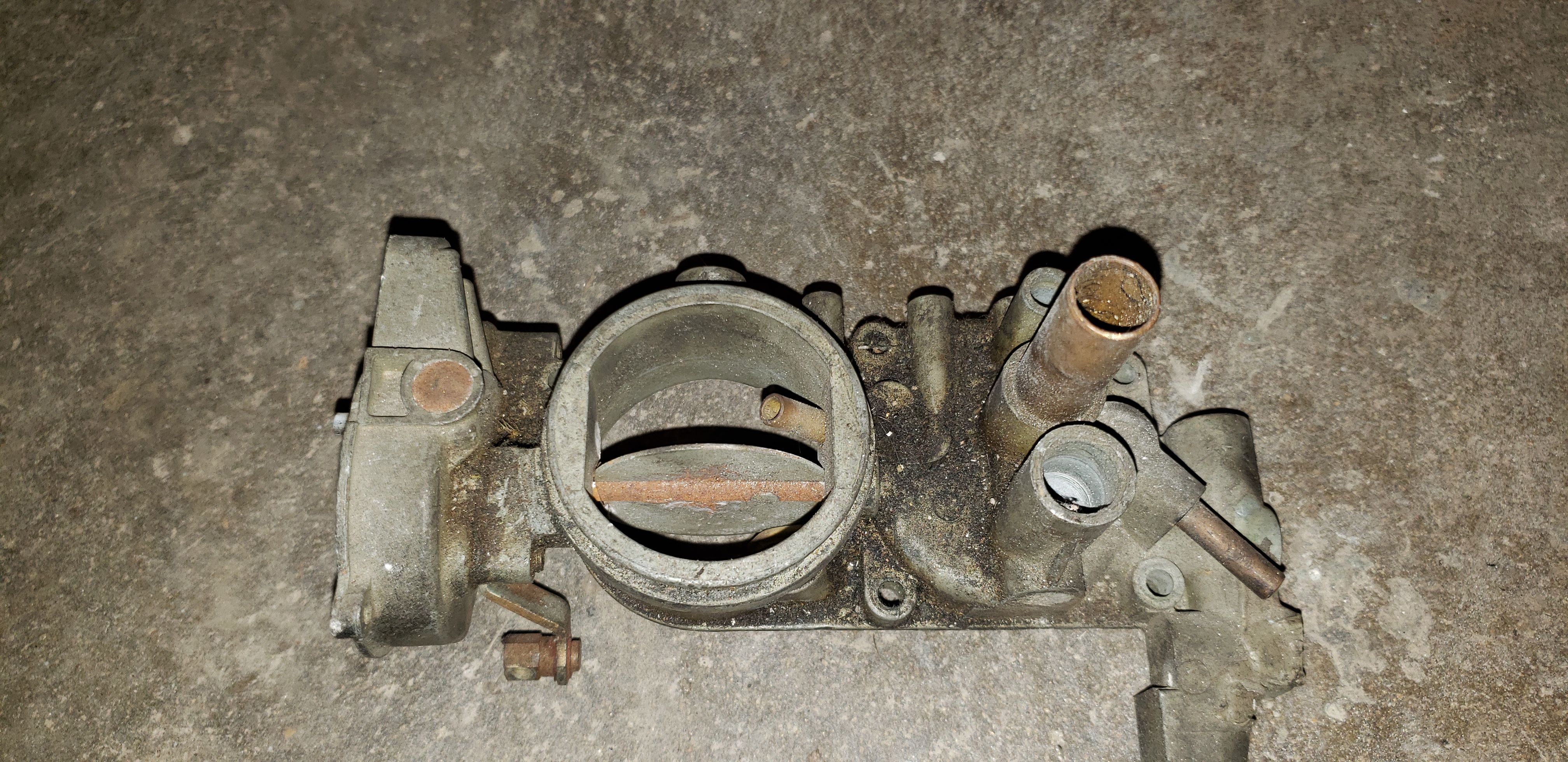