Lately I’ve been seeing vehicles with the wrong pedal assemblies installed in them. Some websites offer the late pedal assembly – 66 and up – but state that it’s correct for all non bus models from 1958 and up. This is wrong and putting the wrong pedal assembly in your car will make it impossible to adjust the brake push rod, adjust the clutch properly, and you’ll never have the proper at-rest orientation of the pedals. Proper pedal orientation and function is only possible with the correct pedal assembly. And a whole bunch of other stuff, which you’ll find in the text below. If it seems like a lotta text, it is. But that’s what it takes. I recommend reading the whole thing before you do anything.
Pedal orientation is fine tuned using the pedal stop that’s bolted to the floor. When adjusting the stop, since it may have not been touched for perhaps the last 50 years, you need to remove the pedal assembly and remove the stop on the floor. If the bolt seems so tight it feels like it’s gonna break, heat the captured nut on the outside/bottom of the floor red hot. The bolt will probably come loose. If it breaks, drill out the remnant and use a longer bolt and a nut. Messing with a helicoil is not the best option because there’s not really enough depth in the nut to accommodate the entire length of the helicoil. Don’t forget the washers. If the area is mangled or rusted out, you’ll probably need to weld. Realize you’ll need to put the stop in exactly the same place it was in when the car was manufactured so you can adjust the pedals right. You’ll need look at another vehicle that uses the same type of pedal assembly as your car and measure to determine the correct position for the stop bolt hole. Clean the area real well. If anything, get all the sand and caked on dirt out. Paint it with spray paint. There’s also a brush on product called Zero Rust and many other options. Regardless, load it up with paint. When reinstalling the stop, put anti seize on the bolt and the bottom of the stop. Then, you can add a dose of WD-40. You want the area real slippery for the stop to slide around easily when it comes time to adjust the pedal positions. If the stop is rough on the bottom from rust, sand it to smooth it out a bit. Do the same for the floor if necessary.
Disassemble the pedal assembly and grease it well. You’ll need a circlip pliers. If the brake pedal wiggles a lot due to the bushing in the pedal being worn, it’s easier to replace the whole assembly. Or you can make a bushing. I did this once on a 57 bug using a piece of brass stock. I used a lathe to drill the initial hole and cut it to the proper outside diameter and spend quite a bit of time filing/sanding the hole bigger and bigger until it just fit over the shaft with no wiggle.
Pretty much every single old Volkswagen, whether you think it needs it or not, needs the pedals lubed. Most haven’t been lubed since the car was new. After you grease the pedal assembly, remove the clutch cable and the accelerator cable. For buses, remove the clutch pedal and brake pedal then remove their respective levers/pivot shafts and grease everything up real nice. The messier it looks when you’re done, the better. Grease prevents rust.
If you’re working on a bay bus, regardless of year, use the early bay clutch cable. Ask for one for a 71. It’s in the middle of the range that if fits so you’ll probably get the right one. The proper cable for, I believe 1976 through 1979, is way too long. You’ll get very little adjustment out of it. The adjusting nut may need to be adjusted nearly to the limit the day you put it on new. When it stretches and you re-adjust, you may run out of threads. The early ones work perfectly since they’re a bit shorter. You’ll have to pull the clutch release lever forward while pulling the cable towards the rear of the vehicle to get the wing nut to start. Awkward but possible. Having helper holding the pedal pedal up is an option. Or pull up the pedal and clamp vise grips at the base of the pedal. It’ll stay up nice.
Lube the the return springs too. The clutch pedal return spring is on the transmission and the brake pedal return spring is on the brake pedal pivot. Grease helps keep springs from breaking due to rust. They may last forever with a nice grease patina. And always grease first, then add oil. Grease doesn’t stick to oil, so grease first, then oil. The oil goes where the grease won’t.
The reason I’ve been seeing non-bus vehicles (so far, only bugs) with the wrong pedal assemblies is because some websites sell pedal assemblies for these vehicles and state their pedal assemblies, complete with clutch pedal , fit from, for bug for instance, from 1958 thru 1978 vehicles. You got that? They come with the clutch pedal. That’s pretty interesting because, usually on the same page, the same website may offer the very same clutch pedal by itself and state it fits from 1966 thru 1979.
What?
Que?
Kang-go-lang?
Gobodingdong?
Where’s Dr. Spock when we need him? Oh … right.
The only thing that’s true here is that the clutch pedal fits from 66 thru 79. And that’s all these pedal assemblies fit too. And people are buying these things for their early cars and thus the brakes are never right again (original early, correct brake pushrod will not work properly with these pedal assemblies either and using the pushrod from a later model – compatible with the late pedal assembly – will not solve anything). And you’ll have less throw for both the clutch pedal and the brake pedal. You’ll probably have to tighten the clutch adjustment so tight that the cable is actually tensioned with no slack (it’s as if your foot is pushing down on the clutch pedal all the time, which your father told you to never do when he taught you to drive in the ’54 that you wish you still had) just to get the vehicle to shift. But then the clutch might slip. Because in this condition, the clutch is partly disengaged. Not good. Read on and see all the nasty things this condition can create.
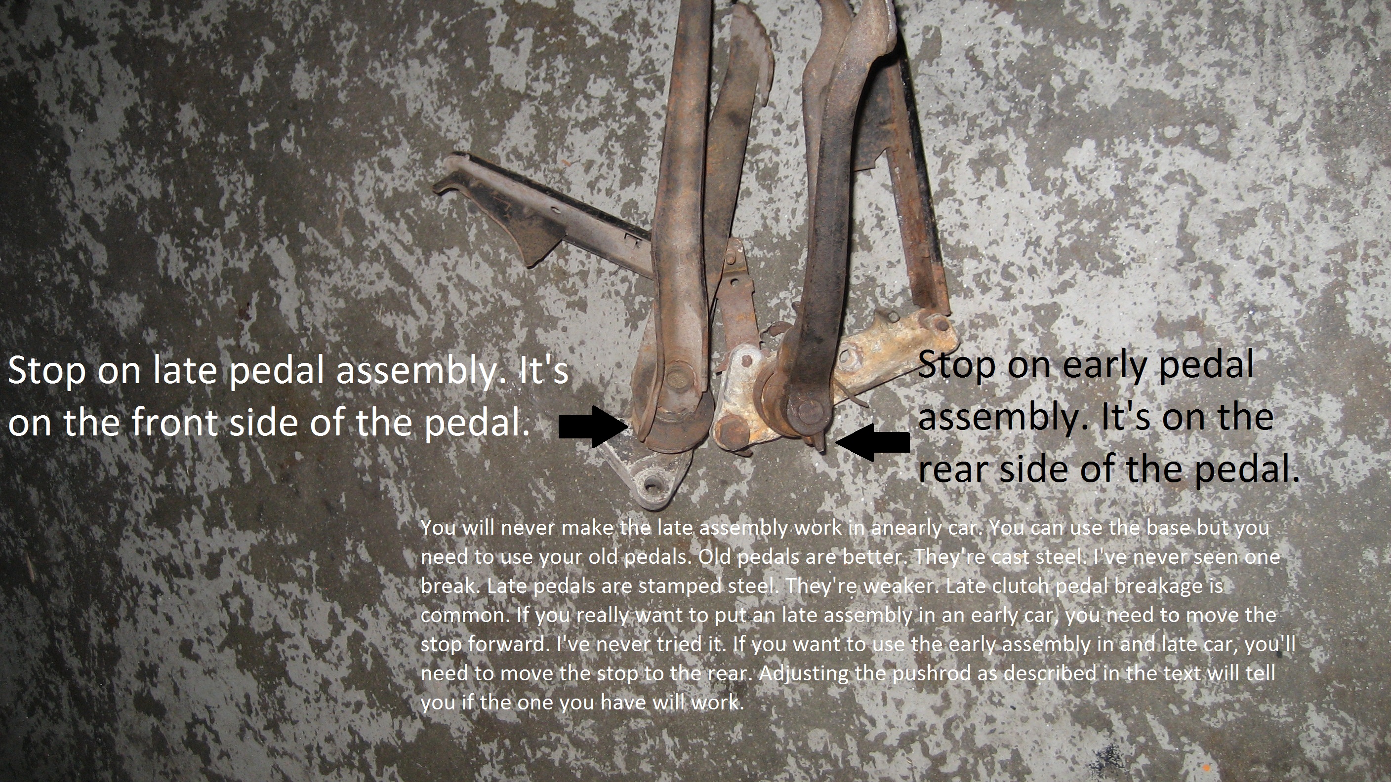
This pic shows the difference between the early and late pedal assemblies …
Changing the stop on the floor won’t change anything. The stops are all the same from 1958 I believe. The slotted hole in the stop allows you to move it forward and backward to adjust the “at rest” (fully upright) position of the pedals. It also keeps them from swiveling all the way towards the driver where the pedal pads would be facing the floor. They can’t easily go all the way to the floor because the brake pedal to master cylinder pushrod jams on the top side of the master cylinder as the brake pedal move moves back with out anything to stop it. This is not by accident. It’s designed that way. Kind of a fail safe mechanism.Looking at the pic – it’s pretty self-explanatory. The stops on the pedals hit the stop on the floor when they’re in the rest position. with a slotted hole. The late assembly will never come all the way back to rest position with the stops located on the opposite side of the pedals than as original. After all, the stops on the pedals are about an inch apart when comparing early to late. That’s a lot.
But still, if the stop bolted to the floor disappears or the floor under it rusts away, the stop function does not exist and with the pedals leaning towards the driver much closer to parallel to the floor vs the correct position of about 12:00, it can make rather hard to place your foot on the pedal instantly. Not good. And it’s not out of the question that one might apply the brakes with this condition and find the pushrod will not push the piston in the master, but push against the side or end of the master or the surrounding vertical part of the floor pan. It would be as if one was pushing the brake pedal against a rock. No stopping would occur. Crashing – highly probable. Very dangerous. Unlikely, but far from impossible.
And the correct brake pedal pushrod will not work right with the wrong pedal assembly. Your brakes will never be right. And anything wrong with the brakes is a safety issue. You just can’t mix this stuff up. Can’t make it up either. This kinda stuff permeates the industry. You gotta be careful whenever you by from real big websites.
If you really need another pedal assembly, buy used from someone who can sell you the right part. Apparently the multi million dollar revenue websites that are selling this stuff aren’t really paying attention. And I’m not splitting hairs here. These pedal assemblies are not interchangeable and it’s pretty obvious just by looking at the pic.
If you want this stuff to actually work right, you gotta use the right parts. And whether you need to replace any of this stuff or not, realize that simply greasing your pedal assembly (removal and disassembly required) makes a huge difference. The day water flows up hill will be the day just squirting oil at this will have any effect. You gotta take it outta the car and then take it apart. Most of them haven’t been lubed since the day the car was made. Which is one of the reasons there’s a market for new pedal assemblies. Lack of lubrication kills the hinges on the gate in your backyard and it kills the hinges that the brake and clutch pedal swivel on.
Pedal assemblies lead a hard life. They spend it’s entirety getting stepped on and pushed on real hard with no regard for their pain or comfort. The driver’s wet shoes ad to the pain. They drop water on the pedal pivot then it lands in a depression under the pedals that gives room for the stops on the pedals to rotate. So in wet weather, water pools up down there. And in wet weather, it takes a long time to evaporate. So the pedals live over a tiny, intermittent, seasonal lake.
For all but bus, brake pedal free play and at-rest orientation is a combination of adjusting the pushrod and the stop that bolts to the floor. For bus, the stop is a rubber block (it’s actually called a buffer) attached to the bottom of the floor. You can’t adjust the buffer that but it could be missing – fell off due to old age so pedal may actually hit the floor without it. In this condition, the pedal must move farther to push on the master – too much brake pedal freeplay. Caused by organic failure since it’s likely the 50 year rubber buffer just fell off because it was disintegrating .
Now for the set-up for possible future inorganic failure:
It’s not out of the question that at some point in the past, someone with little knowledge realized that there was a lotta free play at the pedal so he/she adjusts the pushrod to take up play. So it must be adjusted longer. But then, there may be only 1 or 2 threads of the male part of the pushrod engaged with the female part. This is very common condition on all models because of lack of understanding of what’s really going on. Except Vanagon since it has no free play adjustment.
The pushrod spends it’s life reliving the same terror as that spider you stepped this morning but the pushrod doesn’t smash. It just feels the pain. It’s under a lotta stress and with just couple threads engaged, it’s more susceptible to bending because it’s so long. Realize the stresses on the pushrod turn it into a lever that works against itself. The longer it is, the greater the levering forces. Shorter, but adjusted properly, translates to rigidity.
And here’s where the set up completes it’s task …
Long ago, I stopped the car at a red light. Moments later, with my foot still pressing lightly on the brake pedal, the pedal just fell to the floor. The pushrod was broken. It was adjusted just like I’ve described above. It was a 64 bug. The male part of of the pushrod broke right where the thin part of the rod – master cylinder end – tapers to the larger diameter of the threaded end. I couldn’t believe it. This is the reason for my fetish.
And it’s easy to strip out 2 threads when tightening locknut (more inorganic failure – of a potentially nice Genuine VW original equipment brake push rod made in Germany that had nothing wrong with it). Likely wiggles a bit under stress, no matter how tight the lock nut. And the length issue. But to be realistic, the end of the male part of the pushrod should protrude at least the thickness of one hydrogen molecule through the female end of hole it screws into in the pushrod. No less. But it’s usually more. If the end is down in the threaded hole rather than at least flush, you’ve got probably got the wrong pushrod. You can’t use it. This applies to any rear engine VW except Vanagon.
Very little engagement of any threaded bolt on any car is like building a 6 foot fence and only burying the fence posts 6 inches into the ground. Should be at least 18 inches. That’s a bit more 4 times the thickness of a modern, pretend 4 x 4. Think about this every time you need to use non original hardware with different lengths as original anywhere on anything. Especially when using studs. Especially in aluminum. Like exhaust studs in the cylinder head. And really think about it when you’re messing with that single link to life on your VW – the brake pedal pushrod.
It’s not out of the question that rust repair to the bus floor may alter the pedal position or there may not be a hole in the new floor to engage the buffer. If so, glue it on 2 or 3 inches behind the hole in the floor for the pedal. When done, find a piece of foam rubber about an inch thick. Cut a piece about 3 inches square. With scissors, cut a slot through it little over halfway across. Put a liberal amount of 3M Yellow Weatherstrip Adhesive on it so you can glue it under the floor. Working under the car, pull the pedal down a bit and slide the pedal shaft into this opening and then let the pedal return to rest position. You’ve just sealed the hole the pedal protrudes through in a far better way than the car came new so why even bother with repros? Do the same for the clutch pedal and the gas pedal. Lasts longer than the repro rubber boot for the gas pedal but the gas pedal boots look nice when installed and they seal perfectly. Realize, no matter how well your heater works, if all the air leaks in your bus add up to a wide open vent wing or door window, your gonna be cold.
You may need to heat the pushrod with a torch if the threads are frozen. Lube it well with anti-seize compound so you can adjust it in-situ after the pedal assembly is installed. If you need a replacement, look on the Samba. Try to avoid any online catalog unless it’s Wolfsburg West.
Here’s a link regarding push rod adjustment.
Also take a look at the hook the clutch cable attaches too. Some of them are nearly worn through because they’ve been operated dry – no grease – for years. The simple step of applying grease to the cable and this hook is often neglected. Putting a new clutch cable in nice and clean right out of the package is fairly clean work. Doing it right – grease fest. But the hook will show very little wear over time with plenty of grease.
I’ve fixed worn hooks with brazing and welding. Brazing rod is pretty much brass. Like many bushings. Brass has lubrication properties just built in. There’s no oil in it like some brass bushings (called oilite bushings), it’s just slippery and real hard. Real hard to file. Might be better than welding. Like metals that rub can gall. Unlike metals – not so much. I’ve never bought a new hook. It’s really a shaft with hook on one end. The clutch pedal attaches to the other end. I’d expect a new repro hook/shaft dealie to be wiggly in the hole it goes through in the pedal assembly. I do know that new repro clutch pedals wiggle a lot on an original hook/shaft dealie. Sometimes these pedals crack – even genuine VW ones. They’re formed from sheet steel. The repros are the same thing – formed from sheet steel. I’d expect a fake have a much shorter life expectancy than a real one. And the real ones – not so great. I’ve replaced quite a few. But now, things are different. The quality of repro parts is real bad across the board. The early pedal assemblies have cast steel pedals. I’ve never seen one break. The earliest versions of these assemblies had a grease fitting. They stopped using that feature in the late fifties. Probably made for a pretty messy grease job.
When a cracked pedal is pushed down, most of the motion is translated into bending the pedal rather than moving the cable and the clutch doesn’t work too good – makes the gears grind when shifting. If not noticed and someone adjusts the cable so it will shift, now there’s tension on the cable when the pedal is up – when your foot isn’t even pushing it. Here’s a list of all the things a clutch cable with tension can cause and why
Damage to the number one bearing – the thrust bearing. The end play adjustment shims. The crankcase, specifically the surface at the bearing bore behind thrust surface of the thrust bearing. The flywheel thrust surface. The rod bearings. The crankshaft. The piston rings.
Why to the above …
The crank moves back and forth along it’s rotating axis when the engine is running. This back and forth movement is limited by the end play which is adjusted when the engine is assembled and the flywheel is installed. When the clutch cable has tension, the there’s no space between the clutch and the release bearing. It is, as previously stated, always pushing on the clutch as if your foot is always on the clutch pedal. So the crank can’t move back and forth as freely as it should. Thus, they flywheel is always pushing on the end play adjustment shims, removing any space between them so there’s little room for oil. But not just between the shims themselves, but also between the shim that mates with the main bearing thrust surface and the other that mates with the flywheel thrust surface. This wears both thrust surfaces, but mostly the bearing since the metal is soft. The flywheel surface wear usually presents itself as shallow stepped wear. The shims also get thinner. Sometimes they get torn up.
As all this is occurring, the end play is increasing. As it increases, the speed of the back and forth movement of the crank increases because with more room to move, it can accelerate to higher speeds. So it slams into the thrust bearing harder. And the rate of wear increases. Eventually, the bearing starts wiggling in the case parallel to the axis of the crank. The wiggle is because the aluminum of the case that behind the thrust surface of the bearing of the crank starts to wear.
Now, with the end play far above the proper amount, the crank starts pulling the connecting rods along with it. They begin to not be perpendicular to the axis of the crank. This accelerates wear on the rod bearings and the rod journals.
The pistons follow the lead of the rods – they have the potential to run crooked on the cylinder. So ring wear is accelerated along with the ring lands on the piston.
All of the above can also be caused by sloppy setting of the end play. Click HERE to learn how to do it right.
The release bearing should only turn when you push on the pedal but since it touches the spinning clutch all the time, wear on it is accelerated.
The constant pressure on the release bearing puts constant pressure on the release bearing fork making it prone to breakage allowing the release bearing to fall away the fork. This can really mess up the pressure plate. And in this condition, the car probably won’t shift but it will move.
All along, the with limited travel of the clutch pedal, the clutch is not really disengaging so there’s more friction on the parts in the transmission – the shift forks, the sliders, and the synchros. So the day you start noticing that your car grinds a little in second, for instance, on the downshift will come sooner than if the clutch was really adjusted right.
Since the cable has to be adjusted tight like a guitar string even when you’re not push.ing on the clutch pedal, there’s increase stress on the the tube the cable is routed through. So the likelihood of a tube securing weld breaking goes up. You’ll need to cut the tunnel open to fix that. There’s a weld next to the pedal assembly, there’s a weld near the handbrake lever, and there’s a weld near the shift coupling under the back seat. You can see it by taking the inspection cover off.
Sound far fetched? I’ve seen all this happen on more than one car. Other things can cause the same thing. Improper clutch cable adjustment for one. Click THIS to learn how to properly adjust the clutch cable. Broken clutch cable tube welds on the clutch cable tube can also start the process because if one’s not aware of broken welds, then one may adjust the cable with no slack (translate to free play between release bearing and a pressure plate) to get the vehicle to shift. In other words, someone keeps tightening the cable until the clutch will shift. This is because with broken welds, pedal movement translates to sideways movement of the clutch cable tube rather than enough motion for the release bearing to compress the pressure plate.
On early type one vehicles, the tube may only have two welds – one at the front and one at the back. It’s designed to work with the early, very weak 180 mm pressure plate on 36 horsepower engines. When a bigger engine, like a 1600 with a 200 mm clutch, more pressure is needed to compress the clutch. With only a front and back weld on the tube, the cable tube moves sideways in the middle near the handbrake cable. You’ll need to weld in a bracket to better secure it. Cut the tunnel open and watch with everything connected and you’ll see it move. You can make it as rigid as you want. The more rigid the tube, the better the clutch will work.
The Vanagon has a hydraulic clutch operating system. There’s no cable. Therefore there’s no free play adjustment. The release bearing operating lever always has pressure on it from the hydraulic cylinder. Therefore, the release bearing is always touching the pressure plate. I mentioned earlier that proper clutch adjustment is done to create space between the bearing and the pressure plate. Vanagon violates this. And since the Vanagon release bearing is the same as all rear engine models from 1971 and up, it implies that all these vehicles can be adjusted with no free play. But it’s very common for the air cooled Vanagon flywheel thrust surface to have stepped wear. Makes me wonder. Regardless, always adjust the cable to aim for space between the bearing and the pressure plate. For Vanagon, you have no choice.
Onward …
Given the quality of the parts today, the best thing is to have someone weld a cracked clutch pedal. The welder will have to grind the crack so it becomes more like a v shaped valley rather than a fracture. That way the weld will hold the two walls of the valley together via lots of surface area contact. Just trying to weld over the crack is like trying to suture an earthquake fault. The crack will happen quickly after welding it if the crack is just “sutured” Anyway, if you’re pedal is cracked and it doesn’t wiggle (likely original if it’s a tight fit, requiring hammering it on), have it fixed. I your hook/shaft dealing doesn’t wiggle much and the hook is still has 1/8 inch or more left at the most worn spot, have it fixed too. Weld, braze. Then file it so it looks like a question mark. Trial fit the cable end on it to make sure it fits well and moves freely without binding through it’s range of travel.
And since you’re working on the brakes, albeit indirectly, and greasing the clutch and accelerator cables while your at it (after all, you’ve got the pedal assembly out – the cables are right there), you might as well grease the handbrake cables while you’re at it. And if you want the brake pedal to be where it belongs, even if it’s the right one, which most of them are, you gotta make sure the handbrake cables are adjusted right. And grease is a prime ingredient to meeting that objective. And sometimes they’re so mal adjusted that one or both can actually be holding a brake shoe or shoes in semi-on position and make one or more brake shoes wear down to metal and tear up the drum while the other shoes may look like new.
And there’s more to it than tightening up the nuts on the ends of the cables. And if the cables are decent, you don’t even have to take the wheels off. Just detach the cables at the hand brake lever, remove the lever assembly, and pull them outta their tubes from under the car. Loosen the bolts fairly loose for the securing cable securing clamps at the backing plate on models so equipped so you can disengage the bowden tubes at the backing plates. These bolts screw into a nut that’s welded to the backing plate (for real old models – fifties – the nut the bolt engages with may not be welded. If this is the case, you’ll have to remove the wheel). Slide the bowden tube up and down the cable. If you see any broken strands on either cable, replace both cables. Cables must match for best handbrake operation, especially the kind with the equalizer bar – 65 and up for all but buses and from mid 72 for buses.. If the bowden tubes are beat looking, you need new cables. Bay buses are probably the most likely to need new cables due to tired, crusty bowden tubes. They seem to degrade more than any other models. And when looking real funky, they can really bind the cable and make the brakes drag but if you’re on tight budget, you can usually get them to free up with generous lubrication. Bus bowden tubes slide out of the backing plates easily. There’s no securing hardware but they can get stuck in the engagement hole. You’ll need to apply WD-40 and twist. If real tight, you may need to heat. Real old buses – they may have a securing clamp like all bugs. Can’t remember. But you get the picture. And it’s covered with grease. Grease is the key.
So let’s grease the cables. Slide the bowden tube back and forth over the cable to get grease in the tube too. Wipe the grease from the cable on the backing plate side so you don’t push a bucketful of grease through the backing plate where it can possibly get on the brakes themselves. A little engine oil is a good thing too. Flows into the windings of the bowden tube better than grease but grease is essential. After this, you’ll also be inserting the well greased cables into the tubes in the frame. The super greasy cables will carry the grease into the frame. Do this a couple times so you really grease the tube all the sway to the opening in the tunnel at the handbrake lever. When you’re done, the tubes in the frame are slippery and the inside of each bowden tube is slippery. Slippery. Ahhh …
Doesn’t hurt to lube the handbrake lever assembly either. Lube the pivot pin on the handle and the pin that the handle swivels on. If you need clips, you can get them in a generic auto parts store. They won’t look like the originals but they’ll the work as well if not better. Bring the pin with you when you shop. You’ll probably need a pair of circlip pliers unless you’re deft with a pair of small, pointed objects to spread the non-genuine clips open. Wipe a little grease on the rod and smear a some on the spring. Put a little on the ratchet teeth too. Put some on the side of the ratchet plate too. It rubs on the side of the handle. Anything that rubs on something else needs lubrication. So don’t forget the ramps on the lever that the cables slide in. Buses have them too. Now install the lever and then the cables – attached real loose – nuts just barely on.
Be absolutely certain the cables are properly engaged with ramps as you install the lever. If they get between the lever and the edge of the opening in the tunnel, you may damage either one of them the very first time you lift the lever.
Now adjust the rear brakes. Do it like the book says but for each shoe you adjust, after adjusting, pump the brake pedal a few times hard. Now check adjustment for each shoe. Then repeat for each of the others. For buses from 72 and up, back off each adjuster all the way – reverse direction for tightening. Unlike earlier model buses and all other models, these adjusters must be adjust a little at a time – 3 0r 4 pries for one shoe, then 3 or 4 pries for the other shoe. Then pump the pedal a few times and check for drag. This may allow you to tighten one or both of the shoes a bit more – higher pedal. Pushing the pedal after adjusting assures the shoe is centralized relative to drum. Then do the other side. A little drag is ok after adjustment. It’s pretty normal. But very, very little effort should be required when turning the wheel by hand to overcome it. If you go for zero drag, you might not have any brakes because the adjusters will be backed off way too far. If you’re unfamiliar with determining drag, do the best you can. When you’re finally done with whatever you choose to do, drive the car a few minutes. Use the brakes aggressively – fast stop from 40 mph, go down a steep hill few times slowing to a near stop, then up to 25 or 30 mph and braking again. Drive normally for a few minutes to let the brakes cool a bit. Then stop on a tiny, tiny grade. Take your foot off the brakes. With the smallest grade, and insignificant drag, the car will roll in the downhill direction ever so slowly. You’ll even feel a slight effect of flat ground at a stop sign for instance. You’ll know.
Now snug up the cables a bit but not to where you think they need to be for final adjustment. Just enough so you can pull the lever up real hard but no so far that the handbrake lever mechanism disengages. You want pulled upon real hard so it seats old cables properly now that they’ve been apart and for new cables, it stretches them so they think they’re broken in. Now leave it for a couple hours.
After your cables are seated or stretched, attempt to adjust them. About 6 to 8 clicks on any non bay window bus vehicle and about 10 to 15 for a bay bus. Realize that a very small amount of clicks before the handle gets real hard to move is not an indication of an effective handbrake. You need a few clicks so the handbrake operator can generate enough momentum to pull the lever or handle in a bus to make the shoes really push hard on the drum. 6 – 8 for a bug. 10 – 15 for a bus. It’s not like it goes on like a light switch. Momentum is a must.
If you find that the adjustment nuts are real close to the end of their threads, meaning you have little or hardly any more threads left to adjust in the future and you’re thinking you have the wrong cables, you might. But if that’s the case, you’ll probably find the nuts adjusted all the way down the threads and still have nothing happening regarding locking up the rear wheels.
But if the wheels are locking up but you have hardly any threads left or future adjustment, you’ve got the right cables. Most reproduction cables are like this because the manufactures of these cables measure with … I don’t know what they measure with. Probably cubits. Or Bic cigarette lighter lengths. Or something else I guess. But it sure isn’t anything you or I measure with because they sure can’t seem to make them the right length so you end up with new cables that may be adjusted to the max the day you put them in new. When they stretch, that’s it. Time for another pair. Couple weeks. Or put washers under the bottom adjusting nuts. NO!! Not a viable solution. Too hard to explain why. Think about it. And, particularly for 1965 and up handbrake assemblies with and equalizer bar (see-saw thing the cables attach to at the handbrake lever), the cables get torn up easy when there’s too much slack – broken strands – then you need new cables again. Early non-equalizer bar cables fare better.
So you’re gonna have to shorten the cables. But you can’t. But you can lengthen the bowden tube. You just put washers over the stepped end of the bowden tube where in inserts into the tube the frame.
Measure the diameter with something and buy a bunch of the same kind. Not 3 about this thick and 6 this thick and 4 that thick. All the same. Thinner the better but not thin like a wavy washer. And flat washers only, no wavy washers. This situates the tube farther back, just like as if you pulled on it by hand while attached at the handbrake lever. Your hand takes the slack out. And so do the washers. But it stays that way. Put on as many washers as you think you need but realize you still need at least some of the bowden tube to engage with the tube in the frame so it won’t flop around. Put about 4 in to start, You may end up with less than a quarter inch but that’s enough.
You can use washers on old original cables too if they seem stretched from 40 years of use. But some that age are still quite usable. Especially split buses and pre-65 everything else. The early, non-equalizer bar design is way easier on the cables than the equalizer bar kind. And if a non-equalizer bar model breaks a cable, the handbrake still works, but only on one wheel. If one cable breaks on an equalizer bar model, you have no handbrake every time one pulls up on the lever, the good cable just gets mangled. See how VW is always improvin’ stuff? It should really be called an unequalizer bar. Lot’s of cars use them. They should’ve left well enough (excellent, actually) alone.
After placing the washers and re-installing the cables, adjust somewhat and pull the handbrake lever up real high and leave it for a couple hours. Then re-adjust. It’ll work for a real long time and with plenty of washers on the bowden tubes, you should have plenty of adjustment left for future adjustments. You may have to do this several times. With too many washers, you may not have enough threads to put the second nut on the cables. And make sure you don’t adjust it so tight that you can only pull the lever up less than the recommend amount of clicks – 7 or so for a bug, up to about 15 for a bus.
After you feel you’ve got them adjusted right, feel for drag at the rear wheels with the handbrake off. If it seems you’ve got a bit more than on one or both wheels, back off one or more adjusters at the wheel. But just one or 2 moves. If any more than that is required, you need to back the cables off a bit.
All VW’s came with a bowden tube for the accelerator cable too. Many are missing. Newer models use a tube similar to the one for the clutch cable. Older ones used plastic tube. Just like you can adjust the effective length of the handbrake cables, you can adjust the effective length of the accelerator cable (and keep it from sawing a slot in the transmission with the toothless hacksaw blade effect) but not with washers – by using a tube of just the right length. Better to make your own if you don’t have one.
You make a bowden tube for the accelerator cable using the white, translucent plastic tubing available at hardware stores and sold by the foot. It’s flexible but stiff, holds a curve which is required, works as good as the real thing, and will probably last forever if you don’t kink it it. If you kink the piece you’re working with, get another piece. It’s cheap. I can’t remember the size but they do have a diameter that will just slide over the tube at the frame and over the tube that goes through the fan housing at the engine. Pull the accelerator cable into the metal tube in the frame. A couple inches still sticking out is ok. Slide the plastic tube onto the tube in the frame as far as you can. This can be quite a few inches. Keep pushing until it won’t move any farther. Make sure it’s on as far as possible so you know there’s no way it can move forward later and mess up your good work. You may want to use a hose clamp on a bay bus.
On other vehicles, the tube may slide quite far onto the metal tube in the frame and enter the tunnel. Make sure that if this is possible, it happens. It may hang up on the pan and fool you. Look at the area in front of the trans from under the car to see what’s happening. You may need to pull the rubber boot out of the way to see this if the boot is still there. You may want to take off the inspection plate under the back seat to get an better look. But above all, you gotta make sure this end of the plastic tube is pushed on as far as it will go. Now place the other end of the plastic tube up to the fan housing and eyeball how much to cut but cut it so it seems too long but may be doable. And you don’t want it to be so short it won’t reach after your first cut. You just need it some reasonable length so you can start fine tuning it’s length. But plastic tubing is cheap. You may blow cut it too short as you’re developing your technique.
Your tube should have a bend like the clutch cable bowden tube has a bend. It’s gotta have a bend. Makes for more precise control of the carb lever movement. Careful cutting – just a little slice at a time with a hacksaw blade – and you can dial in the effective cable length perfectly. The shorter the tube, the longer the effective length of the cable. The longer the tube, the shorter the effective length of the cable. You may have to make a couple tubes to get it right. It’s real easy to cut too much. When finished flood the tube at the engine with oil and and it’ll flow right into the tube. Your gas pedal will thank you and the cable may last forever being shielded from the elements.
Don’t bend the cable (it’s best to use a brand new one) when designing the bowden tube. Since you’re gonna have to mess with the tube as in remove it from the engine end and bend it down for access (careful, no kinks) to cut it maybe several times and maybe start over again because you cut it 1/4 inch too short by accident, or for any reason, you need the cable out of the way. You’ll bend the cable if you don’t remove it from the tube when dialing in the length of the tube. Therefore you’ll need to pull the cable from inside the car far enough into the the tube in the frame to get it out of the way each time you mess with the tube. Then, each time you reinstall to check for proper engagement at carb, push the cable in from the front until about 1/2 inch of cable sticks out at the end of your bowden tube. Insert that 1/2 inch of cable into the metal cable tube at the engine that leads to the carb and be sure the plastic tube is properly engaged over the metal tub at the fan housing. Push the cable all the way to the carb from inside the vehicle, then connect to gas pedal link, pull hard on cable at carb end with pliers to remove all slack, and check effective cable length. With choke and fast idle cam in warmed up position, you want about 1/4 of the length of the cable end to stick out past the cable connector. That way, as things settle in over time, you’ll have plenty of cable end left for maintenance adjusting.
Now check to make sure carb opens almost all the way – full throttle.
Notice I said “almost all the way”. If, with the pedal pushed all the way to the floor, and the lever on the carb is touching it’s stop so it’s cannot rotate any farther, your effectively trying to pull the engine towards the front of the car with the accelerator cable. And this will cause the accelerator cable to break prematurely. If you’re a real aggressive pedal pusher, you might break it on your first test drive. Just make sure you have a little gap between the lever on the carb and the stop. It’s best to have a human push the pedal for you while you look at the carb. Tell them to push hard. A heavy object or even a tool made specifically for this purpose may give you a false reading.
The tube itself engages over the protruding cable tube at the engine and if it’s long enough and has a nice bend, it won’t be able to come off because the tube is longer than the straight line distance between the end of the metal tube in the frame and the engine sheet metal that surrounds the tube at the engine and the stiffness of the plastic will constantly be pushing against the sheet metal around the metal tube and it’ll never jump out of engagement. It’ll have quite a bend when you’re done but it’s the stress from the bend that keeps it on. The bend also makes it easier to control the carb. With the connected with no tube, when you push the pedal down, some of that motion is transmitted into moving the cable sideways before it actually moves the lever on the carb. Bowden tubes give you more control; better modulation. Same goes for the clutch bowden but. And the hood cable (metal) bowden tube. And the gas cap door bowden tube. And the heater cable bowden tubes on buses. And the ventilation bowden tubes on newer Super Beetles. Thank you Mr. Bowden.
If the cable is where you want it, disconnect it from the gas pedal again and pull it forward a couple feet. This is where you finally flood the metal tube at the engine with oil. It’ll run down the bowden tube and some will go into the tube in the frame. It’ll look like you have a new oil leak. And before you began any of this you should’ve greased the cable and ran it in and out of the tube in the frame to grease the inside of the tube. After you’ve let the oil settle for awhile, pull the bowden tube away from the metal tube at the engine, push the cable rearward again so it sticks out of the bowden tube a 1/2 inch or so, insert into metal tube and engine, check bowden tube for proper engagement over metal tube, connect cable to pedal, connect cable to carb, check one more time for a gap between the carb lever and it’s stop. If all is well, you’re done.
Installing a custom bowden tube is helpful in dialing in the effective length of the accelerator cable for non-stock carburetion and will likely result in you NOT having to cut the stock end off of the cable and using one of those ridiculous cable ends that require cutting the cable and securing with a microscopic allen screw that comes with cable end itself. Because, in reality, that tiny screw is really like a tool made to shear the thin cable you’re tightening it against. But the most common problem with this kind of the connector is the fact it’s a microscopic allen set screw which is real prone to stripping the part the allen wrench itself engages wiht. If you must use one of these ends, tap the hole bigger if there’s enough material. and use a bolt. Don’t forget the anti-seize compound.
It can be a hassle if you can’t get the screw out due to stripping of the allen engagement hole or because it’s frozen – do you cut the cable or drill out the tiny, likely hardened micro screw? – when you need to disconnect the cable for any reason? Dialing in your cable length by dialing in a plastic bowden tube rather than cutting the cable is one of the little things that adds to the reliability of a VW. It reduces the chances of breaking the cable to practically zero.
Always adjust the rear brakes before you adjust cables in the future. And for real nice brake job, so the only reason you’ll adjust the brakes is because the linings are worn rather than the adjusters turning by themselves, beat on the threads of the brake adjusting screws with a real big hammer rotating 90 degrees apart for each smashing event. You’re trying to damage the threads. With the adjusting star in a vise, run the the adjusting screw in and out of it a couple times with plenty of lubricant – grease or anti-seize compound – until you come to the conclusion that the adjusters are too tight to turn with your fingers but will still easy enough to turn with your brake adjusting tool. I promise this works!!
Now you’ll hardly ever have to adjust your brakes because the only reason you’ll have to do it is to compensate for lining wear rather than adjusters that turn by themselves. And don’t think the little tabs that engage with the adjusters are that effective. They aren’t and they’re real old. If they’re bent out, you can’t bend them back (use the search function on my home page – type “elastic limit”, then use the find function on your browser for elastic limit). And often broken. Sure beats looking for used backing plates with perfect 50 year old tiny leaf springs. Or trying to replace them (special rivet slammed in with tremendous force). Or NOS ones.
And for the later vehicles where the brake adjustment is performed through the holes in the backing plates and you backing plate holes are no long round but about the same size and shape as a large postage stamp, or a domino – weld fairly thick washers over the damaged holes. It’ll be better than it was new.
Doing the stuff above is just part of putting an old VW in the condition it was when it was new – maintenance is all you’ll be doing. Rather that wondering why you hand brake never seems to work, why your clutch pedal keeps breaking, why you’re always grinding gears in reverse unless you mash the pedal all the way to the floor, why the gas pedal needs tapping to fix a high idle and ….
But if there’s one thing that all old VW’s need more than anything and it’s the most overlooked thing on the whole car – it’s lubrication.
It’s all the little things that add up that make VW’s reliable. Neglect the little things and you’ll always be messing with your car. Take care of them all and you’ll be ready for that road trip to Patagonia along with the expectation you’ll make it there and back with no glitches. The goal of all of the above is not perfection. The goal is to make the care as reliable and in a state where only maintenance is needed – as it was new. Rebuilt engines, transmissions, every single brake part at the wheels new and German – none of this stuff works right unless unless the stuff that actually controls them actually controls them as this stuff did when the car was new. Attention to the little things makes it happen. Along with generous lubrication of every single thing on the car that moves.
Even a drop of oil or two on the hinge pivots for the glove box. Glove box on your pre-1968 bug won’t open unless you pry? If the rubber buffers are gone, buy new ones. Maybe it’ll work right then. If the rubber buffers are there, try rotating them 180 degrees. If it still won’t open without prying, glue a tiny piece of rubber or place a piece of sticky back velcro on each side of the glove box opening where the rubber buffers make contact. Now it’ll open. Seems trivial but it’s not out of the question for a driver to reach over pry to open the glove box for whatever reason and end up hitting a tree due to the distraction. And beside that, it’s pretty cool when the glove box nearly opens itself for you. A drop of oil on that latch can’t hurt either. If it’s original, the grease in it’s nearly fifty years old.
VW’s are unreliable? They need constant attention? Nah. It’s not the car it’s the mechanic. Just follow VW’s lead. They thunk the thin up and they knew what they were doing. These’s cars wouldn’t still be around if they the answers to the 2 questions at the beginning of this paragraph were true.
This entry was posted on Sunday, October 11th, 2015 at 3:02 am
You can follow any responses to this entry through the RSS 2.0 feed.
